


It is not because the interlaced nature of the video. I suspected that some time ago as well, but a field analysis shows same pattern:
top field
bottom field
+ Reply to Thread
Results 31 to 58 of 58
-
-
This is what I get from your screenshot. The histogram looks more "normal".
[Attachment 59775 - Click to enlarge]
Is your video signal Composite or S-video? Can you upload a short clip of your video?
Edit:
On the other hand I think it is possible to find a gain (contrast tweak) which will materialize as an integer rounding such that every other level step is affected which results in the "unusual" peaks pattern.
Edit2, for what it's worth:
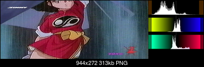
When we grayscale the image (forcing R=B=G or Cb=Cr=128) and inspect the RGB Histogram we see the gaps in the waveform and in the Histogram (RGB format at the bottom)
[Attachment 59778 - Click to enlarge]Last edited by Sharc; 9th Jul 2021 at 03:34.
-
Here 2 samples, from the same recording captured with JVC HR-S9500MS -> S-Video -> Hauppauge USB-Live2 at default proc-amp setting and HuffYUV.
It's a raw unprocessed capture.
The second has a standard field distribution (i.e. not interlaced, coming from the same moment in time), the first is a little weird in its temporal data.
sample1
spike1.avi
sample 2
spike2.avi -
Adding a tiny bit of grain 'smooths' the histogram
Code:addgrainC(1)
[Attachment 59779 - Click to enlarge]
or you may increase the contrast by 1.007 to redistribute the levels
Code:Tweak(cont=1.007, coring=false, dither=true)
Last edited by Sharc; 9th Jul 2021 at 04:30.
-
Maybe its the colour noiseOriginally Posted by lollo

-
Yes, we experimented in the past that a light post-processing remove the pattern https://forum.videohelp.com/threads/401349-GV-USB2-Capture-Stick-What-s-In-It#post2615773Adding a tiny bit of grain 'smooths' the histogram
We were just trying to understand the source of it
-
Uhm.... I suspect then that the histogram for the single channel is of "gap type" as it should be according to skiller remarks, and then combining the full YUV (or RGB) may create the strange saw-tooth pattern. Thanks for the good hint!Edit2, for what it's worth:
When we grayscale the image (forcing R=B=G or Cb=Cr=128) and inspect the RGB Histogram we see the gaps in the waveform and in the Histogram (RGB format at the bottom) -
Scaling and integer rounding (quantization error).Originally Posted by lollo
Take the numbers 16 ...... 235 and multiply with say 1.2 or 0.8, then round to integer and see how certain values get dropped and others accumulate. -
This would produce the gaps and the spikes, sure. But I still do not understand the spiky saw-tooth pattern on top of a distributed levels without gaps. My limit maybe.Take the numbers 16 ...... 235 and multiply with say 1.2 or 0.8, then round to integer and see how certain values get dropped and others accumulate.
-
Again, I think it's the colour noiseOriginally Posted by lollo
-
I don't think that there is anything superimposed on something. Just the regular spikes every other quant level which you can redistribute with changing the contrast or dither by adding noise.Originally Posted by lollo
-
Probably you're right. What worried me is when skiller said that in presence of a spiky histogram some data is lost, and that's why I wanted to fully understand my histograms. It could be a false alarm, I hope...
-
How could the color noise generate that pattern? Do you have a technical explaination?Again, I think it's the colour noise
I have seen it in several captures, with a large set of different VCRs and workflows from friends and from checking the videos posted in the forums. Only common element is the capture card or the chipset in the capture card (I do not remember if VC-500 had same behaviour) -
Originally Posted by lollo
I am really not sure. The only reason I thought it might be colour noise is because it's very noticeable in the footage, and because of the fact that processing removes it -
any light post-processing, even without denoise, remove the patternbecause of the fact that processing removes it
-
So changing the brightness, bobbing it, IVTCing it or re-compressing it removes the pattern?Originally Posted by lollo
-
There is no need to go that far, a simple
reduce it a lot,Code:ConvertToRGB(interlaced=false, matrix="PC.601").ConvertToYV16(interlaced=false)
and if you look to Sharc experiments and my experiments, other simple commands remove it completely! -
It happens when you decrease the contrast or gain. For example say you decrease the gain by a factor of 2/3.Originally Posted by lollo
You can see that pixels with Y values of 102 and 103 have both mapped to 68 -- so there will now be a histogram peak at 68. The same happens at Y=105 and 106, both become 70. You get regularly spaced peaks from the integer rounding (or truncation)Code:before after (truncated) 100 66 101 67 102 68 103 68 104 69 105 70 106 70 107 71 108 72 109 72
Here's an AviSynth script that shows the gaps and peaks from integer rounding:
From frames 50 to 0 you get peaks as the contrast is decreased, from 50 to 100 you get gaps as contrast is increased.Code:function GreyRamp() { BlankClip(color=$000000, width=1, height=256, pixel_type="RGB32") StackHorizontal(last, last.RGBAdjust(rb=1, gb=1, bb=1)) StackHorizontal(last, last.RGBAdjust(rb=2, gb=2, bb=2)) StackHorizontal(last, last.RGBAdjust(rb=4, gb=4, bb=4)) StackHorizontal(last, last.RGBAdjust(rb=8, gb=8, bb=8)) StackHorizontal(last, last.RGBAdjust(rb=16, gb=16, bb=16)) StackHorizontal(last, last.RGBAdjust(rb=32, gb=32, bb=32)) StackHorizontal(last, last.RGBAdjust(rb=64, gb=64, bb=64)) StackHorizontal(last, last.RGBAdjust(rb=128, gb=128, bb=128)) } function cont(clip c, int gain) { ColorYUV(c, cont_y=gain) } GreyRamp() Trim(0,100) Crop(64,0,-64,-0).PointResize(512,512) ConvertToYV24(matrix="PC.601") Animate(0, 100, "cont", last,-100, last,100) AddBorders(4,0,4,0) # so the histogram stays the same scale Histogram(mode="levels") ConvertToRGB(matrix="PC.601")Last edited by jagabo; 9th Jul 2021 at 08:28.
-
Well done!
It's then probably the gain, meaning the AGC (automatic gain control) embedded in the capture card, the reason for the strange histogram, more than the levels (brightness/contrast) adjustements (that I did not touch in capture). Thanks!
Edit: but now, skiller's theory (gaps=no lost data, spikes=data loss, if I did understand correctly) is in danger!
Last edited by lollo; 9th Jul 2021 at 08:42.
-
It depends how one defines the "loss". If we have a lower number of different level steps (=coarser quantization, less bits) the quantization error (difference of precise value vs quantized integer truncated value) becomes larger and the (local) SNR drops accordingly. This inaccuracy and reduced number of levels can be seen as a loss (less details). Therefore it is not recommended to squeeze the histogram unnecessarily.Originally Posted by lollo
In jagabo's "before" we have 10 different steps (100....109). In the "after" there are only 7 distinct levels (66....72). What we visually "loose" in this case is contrast.
On the other hand the empty codewords (gaps) introduce banding, which is however not a "loss" but rather an unexploited potential.Last edited by Sharc; 9th Jul 2021 at 10:27.
-
Not sure I fully understand what you mean: we still have 8 bits, the quantization error happens in both directions, as in jagabo's example. In one direction we produce spikes, on the other direction we create gaps. From the sampling point of view, the consequent SNR degradation should be the same.
-
The gaps from increasing contrast/gain can be removed if you know exactly how they were produced. (Obviously, if you increase the contrast too much you will crush darks and brights, so you will lose information that way.) The peaks from reducing contrast/gain cannot be fixed because there's no way of knowing the original value -- in my example in post #48 there's no way of knowing if the 68 was originally 102 or 103, or if the 70 was original 105 or 106.
-
Hmmm yes, you are probably right. The SNR is not affected as long as we stay in 8 bit and don't alter the analog signal gain.
-
OK.The peaks from reducing contrast/gain cannot be fixed because there's no way of knowing the original value -- in my example in post #48 there's no way of knowing if the 68 was originally 102 or 103, or if the 70 was original 105 or 106.
OK, here we create a gap because we move for example a level 20 to a level 36 and a level 21 to a level 38 and level 37 in the middle is missing.The gaps from increasing contrast/gain can be removed if you know exactly how they were produced.
If the main player is the AGC I cannot go further, but if the main player is the brightness/contrast reduction that we all use to avoid crushing black/white levels, than this means that every time we introduce a spike and we won't be able to reproduce the exact data later. Interesting.
On the other hand, when we expand the levels (something that is just an experiment, I do not think that somebody is doing this at capture stage) theoretically we could recover the gap! -
Not only this but also to obtain Y'CbCr values which will - when converted to RGB - produce legal RGB values. This can be more of a headache than just avoiding clipping or crushing in my experience.Originally Posted by lollo
-
Great explanations guys, @Sharc and @jagabo.

In the end, if the captures look visually pleasing, I wouldn't worry too much about any weirdness that the AGC might introduce. There's most likely no way of changing it on the hardware level.Last edited by Skiller; 9th Jul 2021 at 19:46. Reason: typo
-
Do these spikes really matter? Like it's the analogue footage you are working with, they really don't make a much of a difference
-
They really do not matter a lot. But to say that, we needed to understand what's happening, and thanks to skiller, Sharc and Jagabo we may have found an explanation. Thanks to everyboby for the constructive discussion, and my apologize to the OP for having used his post for my debug!Do these spikes really matter? Like it's the analogue footage you are working with, they really don't make a much of a difference
 Quote
Quote
Similar Threads
-
Capture Codec Setting, Crushed Black Levels, Histogram use
By Smells_Like_Feet in forum Capturing and VCRReplies: 8Last Post: 10th Aug 2020, 11:31 -
Adjusting IRE Black Levels with Sony DV Camcorder Pass-Through Capture
By VideoDoc in forum Capturing and VCRReplies: 8Last Post: 15th Apr 2020, 05:34 -
Adding a new External Capture Card to my Hauppauge Colossus Internal Card
By MounaLafi in forum Capturing and VCRReplies: 30Last Post: 21st Feb 2019, 15:40 -
Adjusting H.264 Levels from .mp4
By chris319 in forum Newbie / General discussionsReplies: 49Last Post: 26th Sep 2017, 15:33 -
Can't capture signal from JVC HR-S9911U VHS deck into Hauppage capture card
By vhscapture in forum Capturing and VCRReplies: 3Last Post: 18th Jul 2016, 13:07