


Hi guys-
I have this big Sanyo TV that only has an RF connector, so my hookup was to run the DVD unit thru an old VCR to get the 3/4 RF channels. Not an elegant kludge, but it worked...
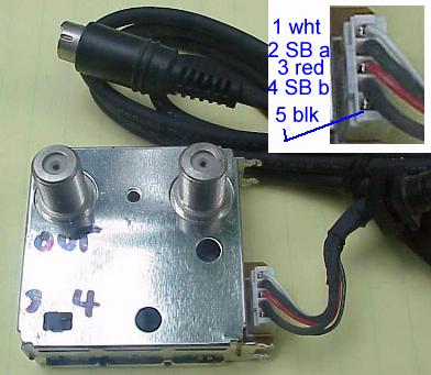
I found an old RF modulator from a Radio Shack camcorder- its tiny enough to fit inside the DVD unit and simplify the rig.
My problem is ID'ing the pinouts on the unit- there's only 5 wires, I'm thinking there is a common ground, a + 9-12 power lead, an audio out, a video in & a video out.
The unit is a Realistic RF Adaptor RF-152, made in Japan by Jalco. Posting a picture...
I'm thinking the two fat wires are the videos, red is power, white is audio, and the thin black is a common ground for all.
This was for a camcorder and has about a 10' cable ending in a PS-2-like connector with 8 pins and a shield.
I'm mostly wondering about how to sherlock which video is which, and if I can parasite the power for it from the DVD mobo...
thanks for any help!
+ Reply to Thread
Results 1 to 11 of 11
-
-
As you rightly suspect, the red will almost certainly be +ve power but more likely 5 volts than anything higher. Check with a meter as you may also find that the two thicker black wires are connected together and are ground (the ground will also connect to the can of the unit). Once you have identified the +ve and ground, you can then power it up and have a play around. My guess would be white for video and black for audio. Try it, you won't do it any harm if you get them the wrong way round. If you connect video to the audio input you will be able to hear the video signal and if you connect the audio to the video input you'll just get strange patterns on the TV secreen.
-
...and be aware that you may have to re-finetune your tv (ch 3 or 4)
Losing one's sense of humor....
is nothing to laugh at. -
Member

- Apr 2004
- Death Valley, Bomb-Bay


Setting your RF modulator is fairly straightforward:
First: Just plug your cable/vcr output into its cable input connection of the RF modulator and the DVD player into the RF modulator's AV inputs.
Second: Connect a standard cable from the RF modulator to your TV.
Third: Select either the channel 3 or 4 output on the back of the RF modulator.
Fourth: Turn the TV on and the RF modulator will automatically detect your cable input for the TV. When you want to watch your DVD player, just put the TV on channel 3 or 4, turn the DVD on and the RF modulator will automatically detect the DVD player and will display your movie. -
That would be fine if he knew which connections were the AV inputs......Originally Posted by Marvingj
That was the original question. -
Are you concerned about losing stereo sound? The VCR route probably preserved stereo but with only a white audio wire, I would doubt it.
-
Thanks guys- I think there's a way to pure logically determine which wire is which. There was this analog repair guy who felt you could that with anything up to about 10 wires...
Richard- thanks for the heads up on the 5 V possibility... good advice all round.
tr- the TV is only mono; I adaptered an old set of powered computer speakers to the VCR audio outs- they give astoundingly good sound- very close to home theatre quality, just not as loud!:]
anybody got a sense of whether the typical PS in a DVD unit could handle the additional draw of an RF modulator? it's tiny, right? -
It should not be a problem for the recorder power supply. Here is a typical spec for a modulator,

25 mA is not much current for a +5V power supply. The ability of a power supply to supply current drops as the temperature goes up, so designers have to design the power supply to supply the needed current at the maximum expected temperature for the unit. Most recorders can work with ambient temperature of up to 40 degrees C. so at room temperature of 23 degrees C. the power supply can supply more current. -
Thanks TR! Its good to know the RF unit doesn't need a precise voltage.
Speaking of heat, I think these slim low DVD chassis are way under vented... -
I hope you're going to post back your findings - I like the Heath Robinson approach to ressurecting old gear !!

-
Hi, I have just used a similar RF adaptor to link my CCTV to my TV system. The connections are exactly the same but I have found that the red is the audio input, white is video input , the two thick black wires are audio and video grounds and the thin black wire is the positive supply. The negative supply is also connected to the common grounds. The thin black wire is internally connected to a TO92 chip which has the marking 8045 on it, which I am assuming is a 4.5v regulator. I have tested the output and it remains at around 4.6 volts with inputs ranging for 5-15 volts, which supports what trhouse stated earlier. My system is working well with a supply voltage of 12volts and has been so for a couple of weeks now. Hope this helps.
 Quote
QuoteSimilar Threads
-
AC to USB Power Adaptor
By Frank-0-Video in forum ComputerReplies: 2Last Post: 4th May 2011, 10:49 -
power adaptor
By n0p3 in forum Newbie / General discussionsReplies: 1Last Post: 1st Jul 2009, 22:21 -
Photo Frame, and figuring out best dimensions
By snafubaby in forum Portable VideoReplies: 2Last Post: 21st Dec 2008, 04:37 -
what adaptor for protable hardrive should i use.
By krnjason in forum ComputerReplies: 7Last Post: 28th Nov 2008, 08:45 -
AC adaptor for PANASONIC PV-GS39
By crocker5731 in forum Camcorders (DV/HDV/AVCHD/HD)Replies: 0Last Post: 2nd Sep 2007, 15:59