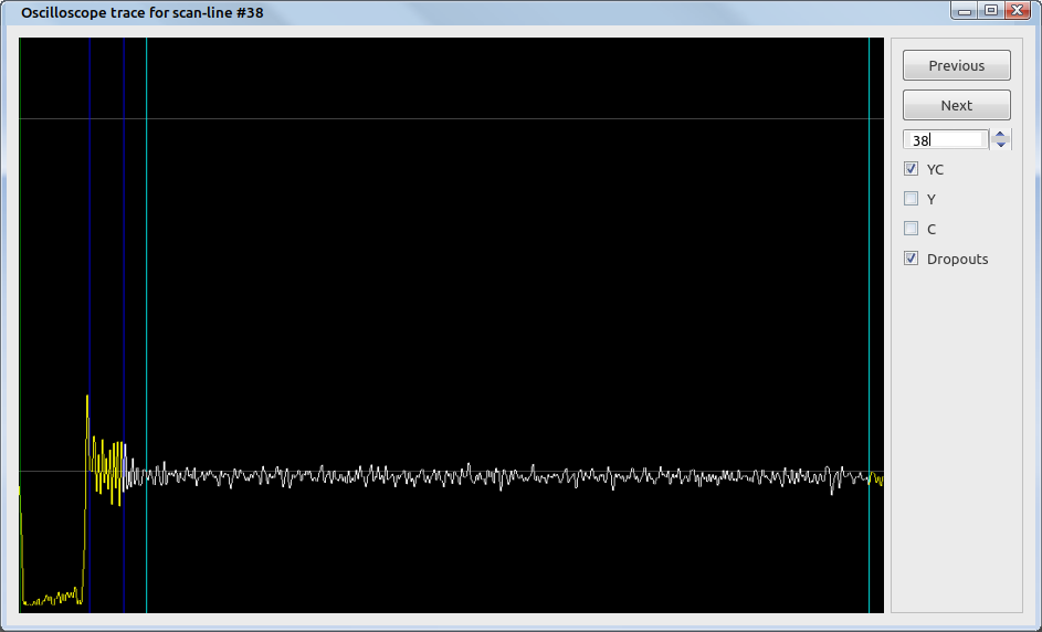
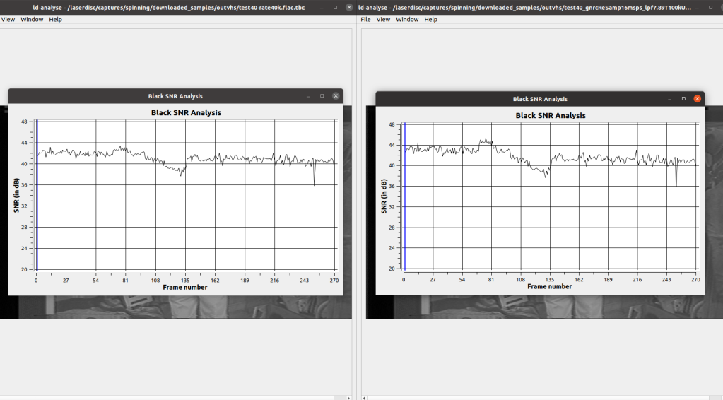
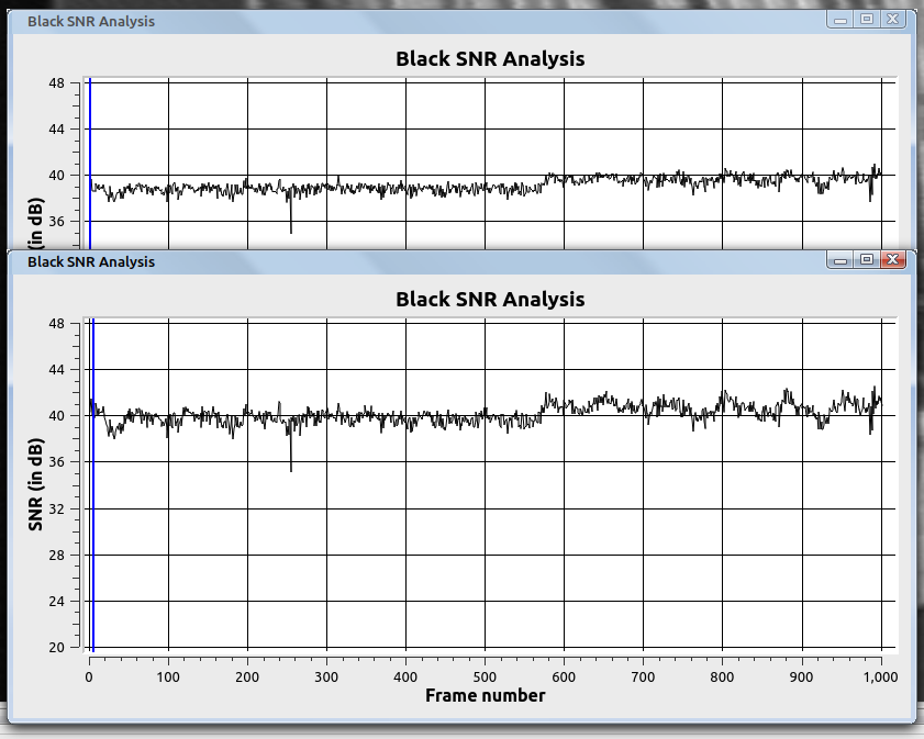
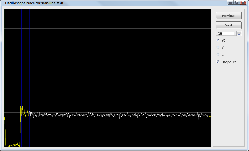
I tested the "combined noise" theory with another tape. I did not see any noise reduction by combining the luma and chroma files this time around. So this effect is going to be tape specific... where in a certain specific situation if there is chroma noise superimposed on the luma signal with an inverted phase. This would allow for phase cancellation of the noise when combining the luma and chroma channels. Could be caused by a reflection in the RF capture chain when that tape was captured, or possibly an error during the factory duplication process of that movie.
Line from luma TBC file:
Same line from combined TBC file:

+ Reply to Thread
Results 841 to 870 of 1200
-
-
Here is another comparion.
VHS-decode overall quality is much better, but the image is "ghosted left".
The channel logo and the text is much better with the conventional capture. (I think this "error" is due to the ghosting effect)
VHS-Decode:
[Attachment 63902 - Click to enlarge]
Conventional capture method:
[Attachment 63903 - Click to enlarge] -
I can't remember fully but I believe the issue is related to phase delay in the code? Or the captured signal?
-
I mean it's not really a simple "fix." As was mentioned a few times the phase delay is likely caused by some frequencies being sampled sooner or later than other frequencies. This would likely result in certain shades of gray (frequency modulation) to appear shifted to the left or right vs. a standard VCR. The exact signal path from the head amplifier to the rest of the machine is going to be different than when tapping the RF test point with a Conexant card or Domesday Duplicator. Plus, the exact VHS specification is not 100% known. There's definitely some guess work with regards to de-emphasis and many other aspects.
For me, the software approach has several advantages over a typical VCR playback. I demonstrated comparisons a few pages back. But it's not going to be for everyone. Both solutions have strengths and weaknesses.Last edited by Titan_91; 23rd Mar 2022 at 09:12.
-

9954tony and I are pleased to present a new tool, Ruxpin decode. It's a GNU Radio flow graph that will take a luma TBC file from vhs-decode and extract TV Teddy voice data as a WAV file from the video signal. For the first time, Teddy's voice can now be decoded in software, allowing complete digital preservation of the TV Teddy experience! This is now part of the vhs-decode GitHub repository, thanks to oln for uploading this.
The readme document explains how to use this tool.
https://github.com/oyvindln/vhs-decode/tree/vhs_decode/tools/ruxpin-decode
This is also attached.Last edited by Titan_91; 10th Apr 2022 at 18:23.
-
This chroma phase cancelation thing has still been bugging me. Why do checkerboarding artifacts only show up on some tapes? Why does the same tape exhibit different amounts of checkerboarding on different VCRs? Why isn't checkerboarding seen when played back normally via composite?
I think the VHS standard itself answers all these questions. I did some more reading on crosstalk, and determined this technology is pretty susceptible to crosstalk between tracks. U-Matic does not suffer from crosstalk between tracks, as the tracks are more spaced out. But VHS, in order to maintain adequate recording times and slow enough tape speed, does not have these "guard bands" between tracks.
The phase rotation of the chroma signal helps combat crosstalk issues between tracks on the chroma channel. But in our case, the chroma signal itself seems fine. After phase correction, the color is always correct and consistent. The source of checkerboarding always shows up as a chroma pattern in the high frequency luma signal. Spectrum plots suggest upper harmonics of the luma/chroma signal are being captured. And an upper harmonic of the chroma signal is likely aliasing the luma signal, causing these patterns in the luma.
But what if the checkerboard patterns are actually from the chroma signal of an adjacent track? That would answer all of my above questions. Each machine tracks differently. All machines internally combine luma and chroma and upconvert the chroma signal after demodulation, the same thing when combining/summing the two TBC files. If the neighboring track's chroma is showing up as a phase rotated pattern in the current track's luma signal, then the chroma signal of the current track will sum with this interference pattern and cancel it out, leaving only clean luma and working chroma from the current track. What is left is just luma and the higher amplitude chroma signal of the current track, allowing color to still be functional.
This theory blows my mind! Thoughts?
https://electronics.stackexchange.com/questions/173626/video-home-system-vhs-bandwidth/175647#175647Last edited by Titan_91; 29th Mar 2022 at 15:58.
-
There is some checkerboarding on strong color on normal playback to some degree at least on PAL, most visible in EDIT mode. I've not seen the more "high frequency"/crosshatch pattern type on normal playback seen in e.g this post though, that one confuses me a bit more.
Video8, betamax and vhs LP all used a technique where each other field is offset slightly in frequency (half line frequency, called half-shift) which supposedly helped reduced crosstalk as the it would cancel itself out to some extent with Y comb filter (basically just blending a bit of the previous line into the current one). The standard analog noise reduction on VHS SP works in a similar way though without the frequency shift. There's an overview abut it in betamax on page 36-37 here (though the exact process may have changed later when VCRs started using CCD delay lines that would handle the full bandwidth demodulated signal).
Whether or not this stuff we're seeing is crosstalk between tracks or not I don't know though. -
A DC offset is basically undiscernable to our ears. Can you still hear with added pressure on your ears due to altitude? (Yes) Because that is the nearest physical equivalent. You usually don't notice unless the pressure shifts enough and your ears "pop!". Or you experience it for long enough (when not acclimated to it) that you have some minor accummulated fatigue.
Either is a little more noticeable when the pressure on one ear is more than the other, but that's it. And that's probably closest equivalent to a nonlinear offset. Even that isn't exact, because the offset has to do with push vs pull (aka compaction vs rarefaction), not stereo differences.
The only time where it can play an obvious part during the sound chain is when the nonlinearity affects thresholds - in processing, amplification, distortion. The nonlinearity then shows up with a different set of harmonics than one would normally get if the signal were linear around the amplitude axis.
If you are processing (and it sounds like you are), it is best to perform dc offset compensation prior to the processing.
Scott
Btw, this is off-topic so should probably be its own thread.Last edited by Cornucopia; 3rd Apr 2022 at 12:52.
-
-
vhs-decode already removes DC offset, unless you run it with -noclamp (or --no_clamping) set to true.
Internally, this sets a variable named disable_dc_offset.
https://github.com/oyvindln/vhs-decode/wiki/Command-ListCode:luma_group.add_argument( "-noclamp", "--no_clamping", dest="disable_dc_offset", action="store_true", default=False, help="Disable blanking DC offset clamping/compensation", )My YouTube channel with little clips: vhs-decode, comparing TBC, etc. -
-
@wright96d, TBH I thought you were pulling a non sequitur talking about that as relates to Audacity on an audio signal. My bad, now I see you were referring to your video capture and processing it using Audacity, due to its existing audio-like format. I don't know specifically what happens to video in the RF realm, but would venture that the bit about nonlinearity and hartmonics would still hold true, so should be compensated for as early as possible.
Scott -
I tried something interesting on the Tom and Jerry sample. This sample has crosshatching in the strong reds. There is a prominent upper harmonic, so I went into formats.py and changed the luma cutoff frequencies to capture the upper harmonic, instead of the original luma signal at 3.9MHz. Same bandwidth, just did some measuring and added to both numbers.
I then compared the normal signal with the upper harmonic in ld-analyse. The pictures are identical, aside from noise of course. I was trying to establish if the upper luma harmonic came from an adjacent track. If that were the case, the pictures would be different because they would be one field off. That is not the case.
Now, I haven't tried the same comparison for chroma. If I click through the same chroma frame from both signals and see a phase difference... then we will have some hard evidence of high frequency chroma crosstalk in the form of an upper harmonic. But I doubt I will see that. -
-
That is on the final luminance ouput, what it does is align the detected video level at sync to where it's supposed to be (which can sometimes cause issues if it misdetects the video levels).
DC offset in the original signal is removed before decoding though as the luma/brightness signal is high and low pass filtered in the megahertz range, and there is a crude dc removal on the chroma part (+ that is also band-pass filtered) so not sure if remove dc offset in audacity would make much if any difference. -
Oln, is the upper cutoff for the luma filter still 5.3MHz? If so, what is the transition band? As in, at what point past 5.3MHz does the signal attenuate to 0dB before luma is demodulated? I ask because I'm trying to maximize the compressability of my captures with FLAC, and the best way to do this is to eliminate as much of the high frequency noise as possible from my 10MHz of analog bandwidth without throwing away good signal bandwidth and sharpness.
With the 5.3MHz filter I tried forever ago, the full attenuation appeared around 6MHz. So a transition band of around 700kHz. That filter was too aggressive, as we established way early on that there is usable video bandwidth as high as around 7MHz.
https://forum.videohelp.com/threads/394168-Current-status-of-ld-decode-vhs-decode-(tru...25#post2629909
So I'm guessing your upper transition band is quite wide to capture all the needed bandwidth/sharpness without introducing high frequency noise into the picture from the first upper harmonic.Last edited by Titan_91; 8th Apr 2022 at 22:07.
-
I don't know what the exact transition band is but the current luma fm filter on NTSC is a 1st order butterworth bandpass with corner frequencies (that is, where the signal is attenuated to half the value) at 2.6 and 5.3 mhz combined with a 2nd order butterworth low pass at 1.3 mhz and a 3rd order butterworth lowpass at 6.08 mhz. Additionally there is a boost to high frequencies done using a 1st order butterworth bandpass filter on a copy on the filtered signal with corners at 4.1 and 5 mhz, which is multiplied by the high-boost setting (default 1) and added to the signal. As it's low order butterworth filters the transition band is quite wide. I can maybe try to make a plot at some point if needed.
Honestly the filters have been mostly set as they are through trial and error on probably not very good early samples. Tweaked them to be reasonably wide while avoiding any white/black streaks so I'm sure they're not very optimal (on most samples they can be wider really) and could probably be improved a lot by someone with better knowledge about DSP and filtering.
I'm currently looking into sync pulse/level detection code trying to see if I can make it work better on some dodgy samples and maybe speed it up a tad.
One test option I added recently iswhich takes a number from 1 to 6, it makes the vsync serration code use on only every nth sample to reduce processing time (1 is every sample so that won't make a difference obviously). Given that the signal used for sync/level detection is already filtered with a corner at around 0.5 mhz, it shouldn't really affect accuracy much if any since the original signal is at 40 mhz sample rate. Profiling suggested the vsync serration code took a lot of processing time but It didn't help as much with speed as I had hoped though, maybe only like 5-10%. Intention is to make it later do all of the sync detection on a reduced sample but that will take a bit more rework to make it seamless so it's only on one part for now. Feel free to test if it helps a bit though.Code:--level_detect_divisor
Last edited by oln; 9th Apr 2022 at 06:06.
-
Thanks. That side of things is a bit over my head. I guess a good way to find out is to look at the spectrum plots of some of my best retail samples. I do know from analyzing multiburst patterns that vhs-decode does recover 3MHz of luma bandwidth as it is. So we know the luma is band limited to 3MHz before being modulated and recorded on the tape, and we are getting all of the detail that is present in the signal.
Do you happen to have a current NTSC multiburst capture I can play around with? I can try different low pass filtering on the RF and decode, comparing the 3MHz region of the result. If 3MHz is attenuated, I know I'm losing sharpness.Last edited by Titan_91; 9th Apr 2022 at 10:03.
-
I "captured" another CVBS test video and the final result was very flickering.
Here is the link of cxadc file: https://mega.nz/file/dpt0VChL#JdYGUy3n6blfdvDoruTekLtMGzlC_v7ap_XYg3o1GfE
Decoded with this command: cvbs-decode -A -t2 -p --system PAL --10cxadc3 cvbs_flicker.r16.vhs cvbs_flicker
What am I doing wrong? Thanks -
I'll be happy to check it for you. Glad I'm not the only one who has been poking around with composite signals!
I did this comparison with the chroma channels. No difference in the main chroma signal vs. the harmonic. I still think my theory stands in certain cases, and least with inter-track chroma crosstalk in the luma channel anyway. -
I was able to squeeze out a bit more quality from existing captures. I reduced the noise and improved sharpness by a miniscule amount, while saving space. Going back a few pages, VHS's bandwidth appears to go up to 7MHz and maybe a little beyond. 9954tony wrote a GNU Radio flow graph to resample 40MSPS sources (or any sample rate I guess really) down to 16MSPS. This will preserve 8MHz of analog bandwidth which is plenty to encapsulate the real signals we want to decode. The flow graph uses a low pass filter with 7.5MHz cutoff frequency with 100kHz transition band. The low pass filter stage is critical to prevent aliasing of frequencies around the 7.75MHz range and up.
When this is done, at 40MSPS, 9 seconds of RF capture, compressed to FLAC with the best compression setting, is 170.4MB. The resampled 20MSPS file is 107.4MB compressed. And the final 16MSPS resampled file is only 89.4MB compressed. The compression ratio on the 20MSPS file is 0.593. The ratio for the 16MSPS one is 0.617. Despite the slightly worse compression ratio on the 16, 16's file size is 18MB smaller than the 20. That's a difference of 16.75%.
This results in significant space savings when archiving VHS RF long term. But it has another interesting effect I mentioned earlier. In my case with one of the TV Teddy videos, the SNR of the low pass filtered and resampled capture improves by 2dB. The only thing I can think of here is the NTSC vhs-decode filtering is grabbing a bit too much bandwidth of the upper side, leaving room for a small amount of high frequency noise to bring the SNR down a bit. This filtering, for some reason, also makes the image a bit sharper.


https://imgsli.com/MTAzMzY1
The link to the flow graph is here, also attached.
https://www.mediafire.com/file/b0tkgc0nuecmjxt/VHSresamp40to16.grc/fileLast edited by Titan_91; 10th Apr 2022 at 18:25.
-
My YouTube channel with little clips: vhs-decode, comparing TBC, etc.
-
Has something changed with NTSC color decoding recently in the latest revision? I have a tape with multiple cuts where some scenes have working color and others do not. Here's a sample of a short clip with working chroma in the beginning, a black screen, the end of the first recording, and a fade in of the next recording. This second recording has working color for a few brief seconds but as the RF envelope stabilizes, the color "loses sync" and fades away. The only adjustments I made was to set RFParams_NTSC_VHS["video_bpf_low"] = 1500000 and set rfparams["deemph_gain"] = 12 in format_defs/vhs.py.
File is attached. This sample is 16MSPS so you'll need to use the -f 16 flag.
What's really bizarre about this tape is if I don't low pass filter and resample the capture, it goes haywire. Loss of sync, white fish streaks, high levels of squiggly line noise. I confirmed it happens with a previous version as well. My changes to vhs.py are also not to blame. Something is strange with this tape, for sure.Last edited by Titan_91; 14th Apr 2022 at 21:34.
-
Only SP mode de-emphasis is implemented from specs currently. The other modes (NTSC EP & LP, PAL LP) are "guesses". Also try decoding with/without the experimental -nld (non-linear de-emphasis) flag. These modes are recorded non-linear to tape, and a playback VCR will use non-linear filters for its composite/S-Video outputs. vhs-decode currently defaults to linear de-emphasis for everything, as we need a filter expert to focus on this problem.
oln explained this back at the end of 2021. My YouTube channel with little clips: vhs-decode, comparing TBC, etc.
 -
My YouTube channel with little clips: vhs-decode, comparing TBC, etc.
-
I wasn't aware of that --recheck_phase flag. Is it new? The log often shows something like "rechecking phase" when it automatically tries to re-detect chroma phase. Will try this flag.Code:
vhs-decode -n -t 15 -f 16 chroma-dropout-test.flac chroma-dropout-test
-
It's been around since at least the time I got back into this. (May 2021, pg.21 of this thread.) And yeah, vhs-decode will automatically recheck the chroma phase when it detects a signal discontinuity. The flag forces it to recheck on every single frame, instead, for the cases where it misses that a new recording has started on the same tape.
I would only expect this to fix "wrong colors", though. It sounds like you're instead seeing "no colors" at times?My YouTube channel with little clips: vhs-decode, comparing TBC, etc.
Similar Threads
-
what is current "best" file uploading/sharing service?
By hydra3333 in forum Newbie / General discussionsReplies: 15Last Post: 30th Aug 2015, 04:39 -
How i can encode audio of "REMUX" to "BluRay.720p.DTS" wit handbrake?
By VideoHelp4Ever in forum Blu-ray RippingReplies: 1Last Post: 2nd Jul 2015, 12:41 -
[SOLVED] "--ipratio" "--pbratio"+"--scenecut" "--minkeyint" / "--keyint
By Kdmeizk in forum Video ConversionReplies: 14Last Post: 21st Jun 2015, 08:21 -
[Help] Problems with the "Title Button" in the "VTS ROOT" and "VTS Normal"
By kirous in forum Authoring (DVD)Replies: 8Last Post: 1st Nov 2014, 13:31 -
How to convert "Still Image" to "AVC file" (like as Godzilla Blu ray Menu)
By ningnong132 in forum Video ConversionReplies: 2Last Post: 8th Sep 2014, 05:23


 Quote
Quote
