


As for performance, it's pretty slow at the moment. The current bottleneck is certain things in the sync/level detection code, though there is a lot of room for improvement.
The frame drops should be solvable eventually, I don't have a quick fi for it. need to look into the logic that determines how to handle things when sync isn't found etc.
Currently looking into the code that detects line starts. At the moment it just looks at the left edge of the horisontal sync, which is an issue when there is overshoot or noise there causing the start point to be misdetected (I've seen a similar issue on hardware video ICs chips e.g with dvd-recorders/capture cards too). Working on making look at both the start and end of the sync pulse and have some logic to infer which is more accurate. Ideally one could also use the chroma info on NTSC, and on PAL maybe pilot burst signals on formats that have it (betama, hi8, SVHS etc)
I've started working on a gui for vhs-decode, turns out there is a library out there called Gooey that makes it very easy to generate a gui from the python command-line stuff.
I think vhs-decode and ld-decode still works on python 3.8 which is the last version that works in win7 but would have to check to make sure. It runs fine on windows 10 at least provided the needed python libraries are installed (all available through pypi), need to update the readme for it. Loading flac-compressed files needs a ffmpeg or ld-ldf-reader to be available. I have a native windows build of the C++ tools too though I need to update it. Ideally we would have some easily installable/unpackable bundle but not quite there yet.
+ Reply to Thread
Results 781 to 810 of 1200
-
-
Another question

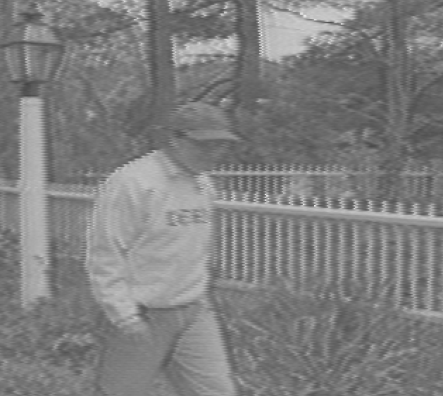
This sample is the same with vhs-decode and conventional capture method.
The vhs-decode picture is more blurry than DV capture.
Is it a wrong vhs-decode setting or what is the problem?
vhs-decode
[Attachment 62539 - Click to enlarge]
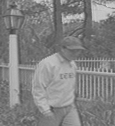
Canopus ADVC-100
[Attachment 62538 - Click to enlarge] -
There is no problem. Your VCR and/or capture box is artificially sharpening the resulting image using a digital filter. vhs-decode preserves what is actually on the tape without any processing. Minus the processing and enhancements done by a VCR, vhs-decode will exceed the quality of a standard VCR for playback. In fact you can see a ghosted outline on the right edge of the E in "BAILE" in your traditional capture caused by the sharpening filter.
Thanks for the questions though and the interest in this project. The above being said, vhs-decode is still under development. Here are some comparisons that show better results using the software method:
https://forum.videohelp.com/threads/394168-Current-status-of-ld-decode-vhs-decode-(tru...25#post2629620Last edited by Titan_91; 25th Dec 2021 at 20:45.
-
Capturing Memories

- Jan 2016
- Member Since 2005, Re-joined in 2016


I think it's too early to say at least it's better than a capture using S-Video and built in line TBC from a S-VHS deck in lossless AVI 4:2:2 YUV2. DV is inferior I agree.
-
I played a bit with the Band-pass filters in formats.py
RFParams_PAL_VHS["deemph_gain"] = 12 (old value: 14)
RFParams_PAL_VHS["boost_bpf_mult"] = 1 (old value: 2)
And the result is much better (with this LP recorded tape)
[Attachment 62563 - Click to enlarge]
old:
[Attachment 62564 - Click to enlarge] -
Nice, oln does that do something similar as the sharpness level -sl adjustment where high frequencies are boosted?
-
This one adjusts the (negative) gain of the deemphasis filter, higher value will attenuate high frequencies more, i.e in practice make the image softer and vice versa. The default is set to match the standard deemphasis filter specified in the VHS spec I think. The sharpness thing is an additional filter with different parameters so the effect will be a bit different.Code:
RFParams_PAL_VHS["deemph_gain"] = 12 (old value: 14)
This adjust some filtering that happens before demodulation .The highest frequencies of the original signal are boosted a bit, which mainly has to do with reducing streaks/black fishes/demodulation noise or whatever you want to call it If it's lowered or set to 0 it could cause more streaks if the captured signal is weak, but on the flip side boosting too much can end up boosting noise or mess with the image too so there is a bit of a tradeoff. It can have a slight impact on how the final image looks too though. This can be set with theCode:RFParams_PAL_VHS["boost_bpf_mult"] = 1 (old value: 2)
--high_boost parameter as well.
Another thing that can help recover a bit of sharpness is lowering video_bpf_low,c it's set a bit high atm to avoid streaks on bad tapes but on most captures it's fine to put it a bit lower to retain a bit more of the lower sideband. (though it may also affect the checkerboard pattern on areas with strong color.)
LP and EP tapes used an additional non-linear emphasis filter on top of what's used in SP mode which isn't properly implemented in vhs-decode at the moment (there is the -nld option but it's not really correct) though I would have thought it would look too sharp/ringy rather than the reverse. VCRs would often do additional sharpening on top of this both when recording and playing back though. -
Very interesting, I'm surprised it makes that much difference. I'll have to do some more NTSC side by side screenshots.Originally Posted by oln


IIRC the sharpness level -sl adjustment (0-100) does something similar, but after demodulation instead. This causes ringing for me so I stopped using it.Originally Posted by oln
This, very much. I believe you said the VHS standard goes down to 1.5MHz, and that's the cutoff I've been using for some time now. Fortunately for me I have not seen checkerboarding artifacts as a result of using this lower cutoff.Originally Posted by oln
I'm not too concerned about how LP and EP content looks considering how compromised the RF signal already is in those cases. It's especially frustrating to come across a tape recorded at EP speed and only like, 20 minutes of the tape was used. Bro, do you even SP?Originally Posted by oln
-
I tested these two luma adjustments myself. deemph_gain changed from 14 to 12. However, boost_bpf_mult was already set to 1 for NTSC. This small change did improve the sharpness noticably for NTSC.
Stock value of 14:
New value of 12:
The difference to me is actually astounding! Here's a full frame shot after the adjustment. I think the contrast improves a little as well.
-
With LP source the TBC is not as good as in SP mode.
Can I fine tune the TBC setting?
[Attachment 62603 - Click to enlarge] -
There isn't some easily tweakable settings for the TBC currently. I'm working on some improvements to take more things into account when TBCing which will hopefully help a bit for cases like this too though.
-
That sounds good. Thanks
-
I've added some code to the code that tries to determine where the start of a line is to also look at the right (end) side of the horizontal sync signal rather than just the start. It seems to help a fair bit on some bad samples like this one from brad/msgohan. It's up on latest git. I couldn't see any samples it caused issues on, but needs some testing to be sure. You can use the
option to turn it off and get the previous behaviour if it does.Code:--disable_right_hsync
[Attachment 62762 - Click to enlarge]
[Attachment 62763 - Click to enlarge] -
That's great! I'm going to try the bad capture I demonstrated again. It's long so I will only decode a small bit at the start.
-
Big thanks oln! Great job. I made a quick test, and the result is very fine. Later I'll post images.
-
One of my favourite projects to check in on from time to time and see amazing progress!
Small question about something I spotted in README.md on the github.
In the "Decoding" section:
As I understand it, this is using flac to compress the raw captured data from CXADC. Hasn't this been captured at 35.8MHz? (or something of this order, depending on settings)Reduce size of captured CXADC 8-bit data (by 50-60%):
flac --best --sample-rate=48000 --sign=unsigned --channels=1 --endian=little --bps=8 -f <capture>.r8 -o <capture>.vhs
The lower 48kHz --sample-rate setting for flac seems to be suited for traditional audio encoding. Does it not remove all the useful RF data when used here?
EDIT: Or maybe it's just a flag, and the actual samples are not impacted? -
Audiovisual Manipulator

- Dec 2019
-
is just indication for any audio player what playback speed should be used to recreate audio. So 48kHz means you have ability to hear what's on the tape but at much lower speed. No samples are affected.Code:--sample-rate
-
Correct. FLAC I think has an upper sample rate limit of something like 192kHz, for audio. Anything too high, like video or tape RF, would not work. That's just changing the playback speed. In fact, I change this flag to 40kHz on my 40MSPS captures. That way I can look at the spectrum and multiply the frequencies by 1000 for ease of observation. Just speeding up the sample rate from kHz back to MHz, so IE the luma signal at 3.9MHz will show up at 3.9kHz in the spectrum view. So I just swap kHz for MHz in my head.
Last edited by Titan_91; 10th Apr 2022 at 21:18.
-
The new right hsync test
[Attachment 62782 - Click to enlarge]
--disable_right_hsync
[Attachment 62781 - Click to enlarge] -
Ooops:
ERROR - please paste the following into a bug report:
current sample: 2548150930
arguments: Namespace(AGC=False, cafc=True, chroma_trap=False, cxadc=False, cxadc3=False, cxadc3_tenbit=True, cxadc_tenbit=False, debug=Fals e, debug_plot=None, disable_comb=False, disable_dc_offset=False, disable_diff_demod=False, disable_right_hsync=False, dod_hysteresis=1.25, dod_threshold_a=None, dod_threshold_p=None, dodod=False, high_boost=0.0, infile='48_hs930_p4.r16', inputfreq=None, length=99999999, level_a djust=0.1, nldeemp=False, nodod=False, notch=None, notch_q=10.0, ntsc=False, ntscj=False, outfile='48_hs930_p4_hb0_p2', pal=True, palm=Fals e, recheck_phase=False, sharpness=0, start=1590, start_fileloc=-1, sync_clip=False, system='NTSC', tape_format='VHS', threads=1, track_phas e=None, umatic=False)
Exception: Failed in nopython mode pipeline (step: nopython frontend)
- Resolution failure for literal arguments:
No implementation of function Function(<function impl_append at 0x7fca95a441e0>) found for signature:
>>> impl_append(ListType[Tuple(int64, Pulse(int64 x 2), bool)], Tuple(int64, Pulse(int64 x 2), bool))
There are 2 candidate implementations:
- Of which 2 did not match due to:
Overload in function 'impl_append': File: numba/typed/listobject.py: Line 592.
With argument(s): '(ListType[Tuple(int64, Pulse(int64 x 2), bool)], Tuple(int64, Pulse(int64 x 2), bool))':
Rejected as the implementation raised a specific error:
LoweringError: Failed in nopython mode pipeline (step: native lowering)
Cannot cast Tuple(int64, Pulse(int64 x 2), bool) to Tuple(int64, Pulse(int64 x 2), bool): %"inserted.f2" = insertvalue {i64, [2 x i64], i1} %"inserted.f1", i1 %".20", 2
File "../../../../../../../usr/local/lib/python3.7/dist-packages/numba/typed/listobject.py", line 600:
def impl(l, item):
casteditem = _cast(item, itemty)
^
During: lowering "casteditem = call $2load_global.0(item, $6load_deref.2, func=$2load_global.0, args=[Var(item, listobject.py:600), Var( $6load_deref.2, listobject.py:600)], kws=(), vararg=None, target=None)" at /usr/local/lib/python3.7/dist-packages/numba/typed/listobject.py (600)
raised from /usr/local/lib/python3.7/dist-packages/numba/core/errors.py:786
- Resolution failure for non-literal arguments:
None
During: resolving callee type: BoundFunction((<class 'numba.core.types.containers.ListType'>, 'append') for ListType[Tuple(int64, Pulse(int 64 x 2), bool)])
During: typing of call at /usr/local/lib/python3.7/dist-packages/numba/typed/typedlist.py (83)
File "../../../../../../../usr/local/lib/python3.7/dist-packages/numba/typed/typedlist.py", line 83:
def _append(l, item):
l.append(item)
^
Traceback:
File "/usr/local/lib/python3.7/dist-packages/vhsdecode/main.py", line 284, in main
f = vhsd.readfield()
File "/usr/local/lib/python3.7/dist-packages/vhsdecode/process.py", line 896, in readfield
f, offset = self.decodefield(initphase=initphase)
File "/usr/local/lib/python3.7/dist-packages/lddecode/core.py", line 3491, in decodefield
raise e
File "/usr/local/lib/python3.7/dist-packages/lddecode/core.py", line 3487, in decodefield
f.process()
File "/usr/local/lib/python3.7/dist-packages/lddecode/core.py", line 2953, in process
super(FieldPAL, self).process()
File "/usr/local/lib/python3.7/dist-packages/lddecode/core.py", line 1464, in process
self.linelocs1, self.linebad, self.nextfieldoffset = self.compute_linelocs()
File "/usr/local/lib/python3.7/dist-packages/vhsdecode/process.py", line 194, in compute_linelocs
[validpulses_typed.append(p) for p in validpulses]
File "/usr/local/lib/python3.7/dist-packages/vhsdecode/process.py", line 194, in <listcomp>
[validpulses_typed.append(p) for p in validpulses]
File "/usr/local/lib/python3.7/dist-packages/numba/typed/typedlist.py", line 344, in append
_append(self, item)
File "/usr/local/lib/python3.7/dist-packages/numba/core/dispatcher.py", line 482, in _compile_for_args
error_rewrite(e, 'typing')
File "/usr/local/lib/python3.7/dist-packages/numba/core/dispatcher.py", line 423, in error_rewrite
raise e.with_traceback(None) -
Definitely a more stable image with the new right sync pulse detection code! I can't compare my other sample as trimming it down in Audacity is too much of an issue, being a FLAC source.Originally Posted by peppi001
-
Agh, I've turned numba optimization for that function for now, it's not a critical part of the code anyhow, so should fix this. There is something wonky with numba and lists causing it to randomly fail.Originally Posted by peppi001
Last edited by oln; 7th Jan 2022 at 12:30.
-
While we're on the subject of bugs, thanks for fixing the white SNR graph in the latest version. Last time I tried it I didn't get a graph. Also, I'm getting better performance now, about 5fps when normally I would get only 2fps or 3fps. Disabling numba maybe?
Last edited by Titan_91; 9th Jan 2022 at 19:34.
-
Hi!
I'm a noob in professional video archiving, but I find this project extremely fascinating - big props for both the hardware and software development so far!
First I was looking for a fast enough ADC streaming device to capture the raw composite or S-video signal from a VHS or Hi8 player for software decoding, TBC and so on instead of relying on crappy cheap USB framegrabbers, but then I found this, which is a so much better approach.
I understand that a big issue with VHS (or most video tape formats) is that there are multiple tracks which are recorded/played by multiple heads simultaneously to get video, linear audio, hifi-audio and the sync track. Maybe the sync track is not crucial because it can be recovered from the video signal and then applied to the audio, but you still need at least 2 simulatneous RF sampling channels (though a much lower sampling rate is sufficient for linear audio). Also, you have to rely on the player's electronics to correctly align the video heads with the tracks, so bad alignment and sync glitches on the tape will degrade the raw RF signal if I'm not completely mistaken.
Ideally we want a "magnetic 2D image" of the entire tape, then we can extract all tracks digitally for any video tape format in existence (provided the specs are documented). I thought briefly of some optical magnetic imaging approach but quickly realized that it would require an insane spatial resolution almost comparable to what's needed to "photograph" a laser disc (let alone the special equipment for precision measurements of the magneto-optic kerr effect and whatnot), so that's out of the question.
Then I thought of magnetic force microscopes used in forensics and that the good old video head inside the VCR does basically the same, just less precisely. The read/write head spins diagonally across the surface and should cover all of it - it's just that the control and linear audio tracks at the top/bottom edge fall into the vblank window and are ignored or maybe filtered out. I haven't captured any RF signals yet, so maybe somebody could confirm whether the video RF signal at the test point closest to the head contains "artefacts" from the audio and control tracks within the vblank interval.
My idea is simply to "dumb down" the VCR and don't use any of its transport and sync electronics at all. With the tape stationary, just spin up the head inside the drum (it can be even much slower than during normal operation) and read out the raw RF, which should give us a diagonal line of the magnetic pattern on the tape. It will actually repeat the same signal each half-rotation, so the signal-to-noise can be substantially increased by waveform averaging. Then after a certain number of averages, the tape is transported by a tiny amount using a stepper motor - it should be less than half of the track width or smaller (10µm or so) depending on the desired resolution - and then a new diagonal slice is recorded at this position. The result should be a very slow but very precise 2D map of the physical magnetization distribution on the tape (projected onto the read head's polarization axis, of course) from where the tracks can be separated out and reconstructed. It should be relatively simple and inexpensive to rig up the VCR accordingly. A slower scan speed of the head allows using slow and cheap USB 2.0 ADCs (maybe some SDR kits) and the stepper can be controlled easily via a serial interface, so any PC can run the whole process. 10µm transport resolution should be feasible with a simple geared stepper motor and it doesn't even need high repeatability, i.e. step jitter can be fixed digitally. We exploit the fact that the spatial information density on the tape is only high along the diagonal track, which is sampled in high-speed by the rotating head, while the transport direction only needs enough resolution to clearly separate adjacent tracks (basically the same concept VHS uses in the first place). This method should also have sufficient resolution for the linear audio track because the video track is at a very shallow angle to the tape edge (7.5°). A small issue is the fact that the different tracks have different magnetic (azimuthal) polarization, i.e. adjacent fields will vary in magnetic strength when scanned by the same head, and the linear tracks (audio and sync) will have a constantly weaker signal than if sampled with their appropriate heads. It shouldn't really matter for the FM encoded video signal and the reduced dynamic range should be more than compensated for by slower scanning speeds and averaging. It should be even possible to use both read heads to complement each other (after digital alignment), which should also provide vector information of the magnetization (for academic purposes, I guess ).
).
So what do you think? Is it possible or a pipe dream? -
Capturing Memories
- Jan 2016
- Member Since 2005, Re-joined in 2016
-
Obviously you don't know how the VCR actually works, By stopping the tape speed to zero the video heads are not going to follow the field tracks, So capstan speed and drum speed are synchronized together to get the heads to follow precisely the tracks, Also you cannot scan the linear audio with video heads, the video head width is larger than the linear audio head gap. and also HiFi audio is recorded in a deep layer, it cannot be read by the video heads, it has to be picked up by the HiFi audio heads. Let's not get into double azimuth heads and head switching. It's not a pipe of dream, It's a pipe of smoke.
This helps you clear the smoke a little a bit:
https://youtu.be/pXFB7lX35KQLast edited by dellsam34; 10th Jan 2022 at 19:02.
-
That's kind of the point of actual tape imaging vs. normal track reading. Think of it as pause mode but with very fine steps instead of frame by frame. If the transport steps are sufficiently small, you get an oversampling of the tracks in the longitudinal direction, so you can reconstruct the diagonal tracks from the 2D image instead of having to align the head precisely with the track. Of course you can't achieve infinite longitudinal resolution because it's limited by the head width (that's the longitudinal point-spread function, in imaging terms), but you can clearly resolve adjacent tracks by longitudinal oversampling, since the head width is about the same as the track width. It might be a problem when trying to image EP or LP tracks with an SP head, but it should be fine using the thinnest (EP) head for everything.Originally Posted by dellsam34
How big is the linear audio head gap? The video head angle is quite shallow, so the effective gap size projected on the linear track is much smaller than the video head width; also one of the heads has a more favorable azimuthal angle which should be close to ideal for the linear track. The longitudinal oversampling and averaging should reduce the noise floor, so even with a bigger effective gap size the original signal should be recoverable (maybe with some deconvolution). Of course I don't know if it would provide any improvement over just using the built-in linear audio head (where you'd also have to ensure constant transport speed between sync pulses), but it comes for free.Also you cannot scan the linear audio with video heads, the video head width is larger than the linear audio head gap.
From what I've read about it, that "deep layer" stuff is just overwriting with a different azimuth angle and a narrower track, right? So the hifi track should be distinguishable from the video track with a single head by using small enough transport steps. The azimuth angle difference is quite large though which may be an issue depending on the FM carrier frequency. On the other hand, FM signals should be more robust against "smear-out" from a misaligned azimuth angle. I guess that's something to find out.HiFi audio is recorded in a deep layer, it cannot be read by the video heads, it has to be picked up by the HiFi audio heads. -
Capturing Memories
- Jan 2016
- Member Since 2005, Re-joined in 2016
-
1-The most optimized way of reading the video tracks with the highest RF signal is the way the VCR already does it, Any alterations brings the RF signal level to almost zero. tape speed, head position and angle, its coil impedance, circuit equalization are all part of the complex equation of reproducing a usable signal from a magnetic recording, You can't just slow down the speed and twist the head and assume you get a reading, that's idiotic. And who would want to playback a tape slower than normal speed, I certainly wouldn't.
2-The audio linear track is read by its own head at 0 azimuth, using the video head with say 20 degree azimuth you get zero audio signal, try turning an audio cassette head just 3 degree and see how muffled the sound becomes.
If you really want to learn about this ancient technology there are a lot of books online, You do have to have some basic physics and mathematics to be able to understand them though. -
The way the VCR already does it is optimized for real-time playback of 50/60 fps with a single pass, it's definitely not optimized to extract the best possible signal from what's on the tape. If you want a convenient live playback device, you're missing the point of this thread, since the software RF decoding isn't even close to real-time either. The best possible archiving quality is limited by the initial RF signal quality you can get and that's not just press play on the VCR. It's entirely up to the user to adjust the trade-off between speed and accuracy, i.e. the longitudinal step size and number of averages - a choice you don't get in real-time playback mode.Originally Posted by dellsam34
How did you come up with 20°? From what I've read, the video head's azimuth angles are +/-6° (or 7° according to Wikipedia, which is probably wrong) relative to the track, and the track angle relative to the tape is roughly the same. So one of the video heads has a net azimuth angle close to 0 (within 1° or so). A small azimuth misalignment of the head gap acts as a low-pass filter, which can be reversed in post-processing since the geometry is known, if the SNR is high enough.2-The audio linear track is read by its own head at 0 azimuth, using the video head with say 20 degree azimuth you get zero audio signal -
Capturing Memories
- Jan 2016
- Member Since 2005, Re-joined in 2016
-
You can't have better performance than the already optimized speed for the reasons you failed to understand, You need to study magnetism, As for audio, the head angle figure I posted including the drum tilt because your idea is using the video head to read the linear audio track.
I think it's better to go back and watch free energy videos on youtube, This is a complicated engineering matter, Even for me as a mechanical engineer it sometimes puzzles me to how complicated some of the brilliant designs JVC engineers came up with to improve the VCR performance such as the Dynamic Drum. We derailed the thread and I should stop going the rabbit hole. -
You're saying averaging and oversampling doesn't increase the SNR because of "magnetism", while every scientific measurement instrument does exactly that? Ever seen a spectrum analyzer?
And the drum tilt has nothing to do with the azimuth angle of the head. It's defined relative to the tape direction.
 Quote
Quote
Similar Threads
-
what is current "best" file uploading/sharing service?
By hydra3333 in forum Newbie / General discussionsReplies: 15Last Post: 30th Aug 2015, 04:39 -
How i can encode audio of "REMUX" to "BluRay.720p.DTS" wit handbrake?
By VideoHelp4Ever in forum Blu-ray RippingReplies: 1Last Post: 2nd Jul 2015, 12:41 -
[SOLVED] "--ipratio" "--pbratio"+"--scenecut" "--minkeyint" / "--keyint
By Kdmeizk in forum Video ConversionReplies: 14Last Post: 21st Jun 2015, 08:21 -
[Help] Problems with the "Title Button" in the "VTS ROOT" and "VTS Normal"
By kirous in forum Authoring (DVD)Replies: 8Last Post: 1st Nov 2014, 13:31 -
How to convert "Still Image" to "AVC file" (like as Godzilla Blu ray Menu)
By ningnong132 in forum Video ConversionReplies: 2Last Post: 8th Sep 2014, 05:23