Nvm, turning off high_boost on this sample made transitions and such look way worse, a bit similar to the effect of setting the vhs-decode rf filters bandwidths too narrow, must be something else then. It seems the 5mhz filter may be a bit borderline at least for the current vhs-decode rf filter setup reducing the top frequencies a bit much.
+ Reply to Thread
Results 661 to 690 of 1200
-
-
Should I go back to the 13MHz filter I was using and rely mostly on the software filters for the sake of future improvement?
-
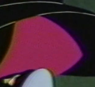
Before I do that, I tried Tom & Jerry again. Results are the same, with the crosshatch pattern in the reds and other high saturation areas. Actually worse, as this tape doesn't do well with the sharpness filter.
Without 5MHz filter:
With 5MHz filter:
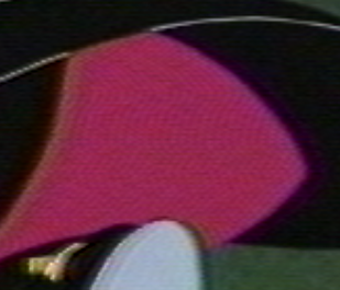
Yep, no more using this filter. Figured I would try to isolate some high frequency noise but it's doing more harm than good to the picture quality. -
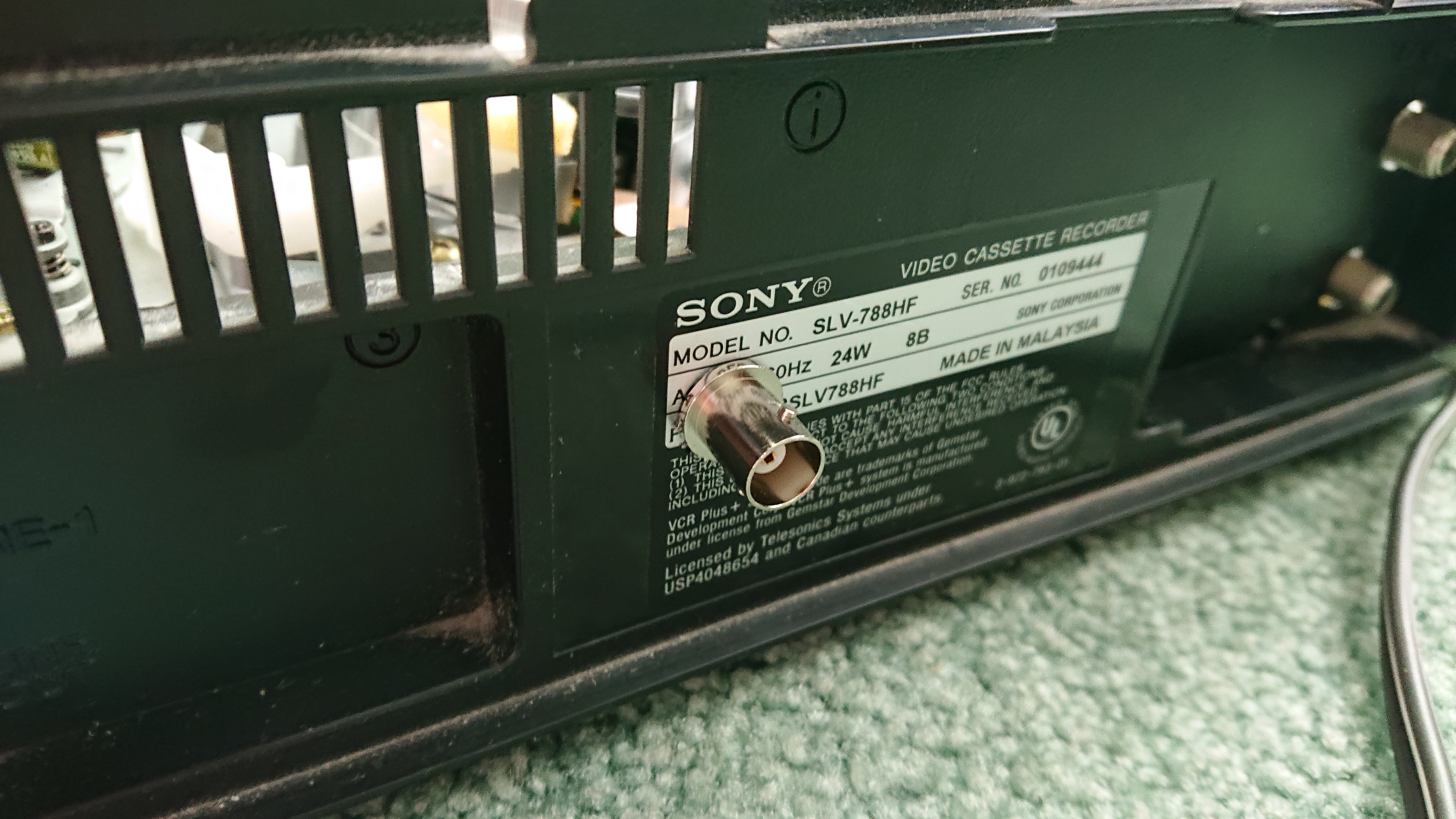
Sony SLV-788HF purchased, will post an update with the results. If it's no good for captures I'll keep it as a spare.
Last edited by Titan_91; 10th Jul 2021 at 15:54.
-
-
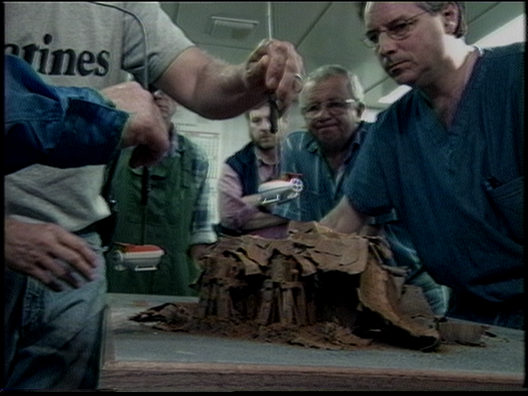
The eBay listing was actually wrong, this machine is a year earlier from 1998 and slightly different from Brad's. However, it has a jog shuttle wheel which is a step above the SLV-779HF. This machine too has an RF shielding cage on the power supply board, with a test point right at the RF amplification circuit which is also RF shielded. This will make for a short and direct RF tap for a BNC port on the back of the machine.
I used the "put-an-alligator-clip-on-the-RCA-cable-and-poke-the-test-point" method for a quick test on this SLV-788HF player. I was very surprised at the strong RF level this thing puts out. It's more on par with my Laserdisc player. Using sharpness level 50, -sl 50. The capture was clipping on the first sample, at gain 31. So I turned the gain down to 25 for sample 2 and it was still too high. For sample 3, I used gain level 1. Looks really good so far, but the crosshatch crosstalk is prominent. This is due to a strong reflection in the upper band, even though I'm using the 10-bit mode with a halved sample rate. This is expected for such a high RF output level. The 13MHz low pass filter "should" clean this up once I install the mod so I can use the filter. But so far I'm very impressed with this machine!
-
If you think about High Pass filter then yes, it usually increase noise but there are different sharpening filters in analog domain - some filters improve transients and they not increase noise level. Also every analog filters has very important parameter - phase response - this can't be ignored - as usually significant oversampling is used in RF capture then usually filtering is not required and processing can be done entirely in digital domain.
-
That's a good point but in this case I'm using low pass filters, not high pass filters. Here's the mod for the Sony VCR:
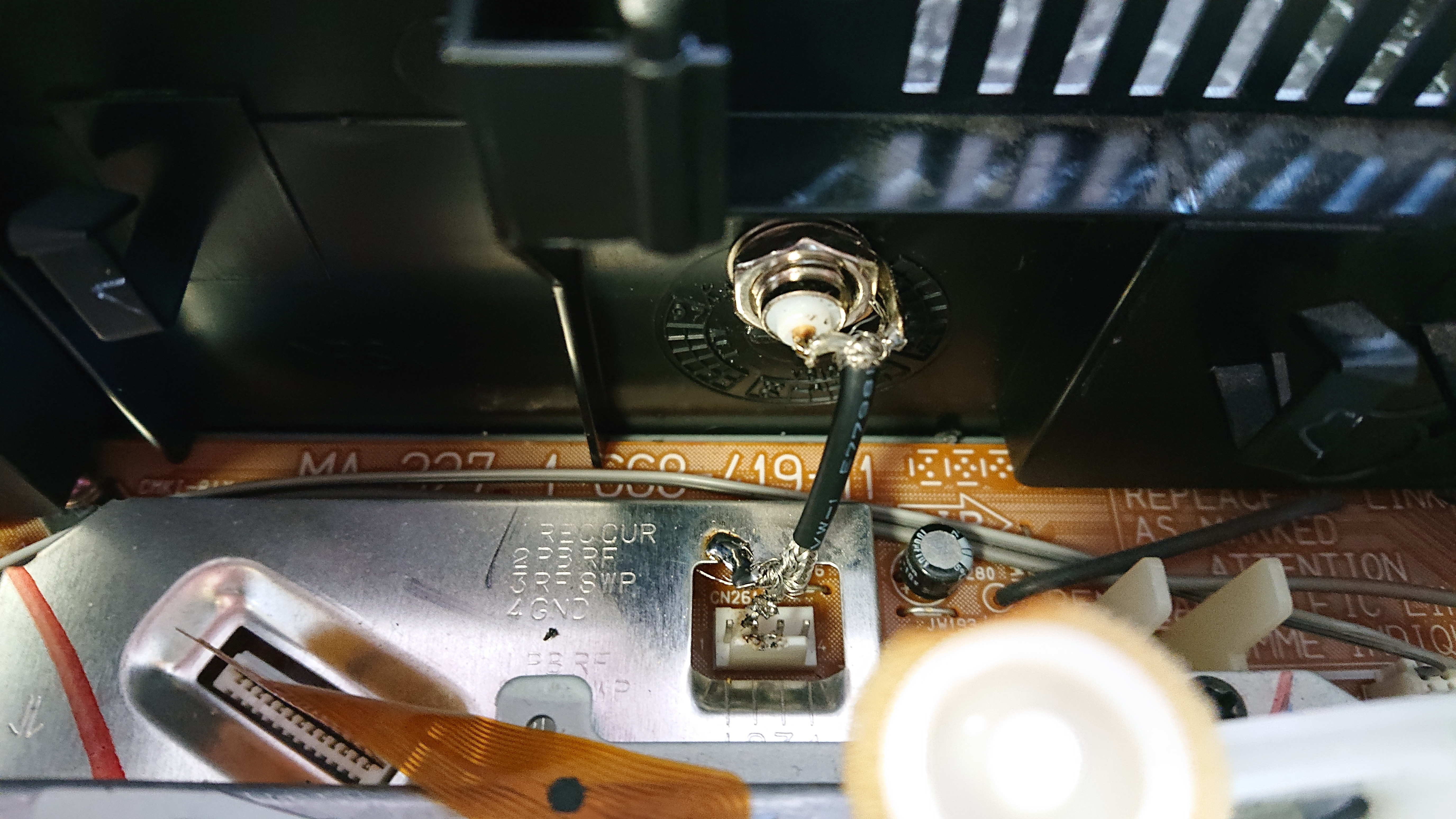
That one was pretty difficult. It was hard to stay clear of the head drum and not destroy the test point header in the process. I did some more testing with the 13MHz filter and just for giggles, went back to using the 5MHz filter as well. This time using gain 15. The 13MHz tests looked about the same, with 36dB of SNR. However, both the 8-bit and 10-bit 5MHz tests are 44dB SNR (wow). Still have that crosshatch pattern, and a ground loop. Will try to solve those issues. The SNR test at least tells me the vertical blanking section is cleaner, but the crosshatch does not appear in this section because the chroma signal does not kick in until the visible picture area. So the SNR measurement does not account for chroma crosshatch interference. -
Interesting stuff, Titan_91. I hope you're able to remove the crosshatch somehow.
My current setup is "mini-hook to BNC" connected to a BNC-to-RCA female adapter, and then an RCA cable into the CX card. Attempting to remove the extra cable, I ordered a BNC-to-RCA male adapter from eBay.
Described as:
Unfortunately, it doesn't actually fit the BNC plug end on my cable. I held them together with my hands and did manage to make the connection. But I don't see any real difference between the captures. I tried an SP mode & an EP mode tape.* Impedance : 50 ohm
* Gold plated or Nickel plated contacts
* Salt spray test : >= 48 hours, enhanced corrosion resistance
* Mounting : machined brass construction crimp & soldered mount
* Connection Protection: Black Heat Melt Shrink Tube Versafit or equivalent
* Operating frequency :0-6 GHZ ( option: 1.2Ghz 2.4Ghz 3Ghz 6Ghz 8Ghz 12Ghz 18G... )
* Technical characteristics : temp. range : -65 to +165 ( PE cable range : -55 to +85 )My YouTube channel with little clips: vhs-decode, comparing TBC, etc. -
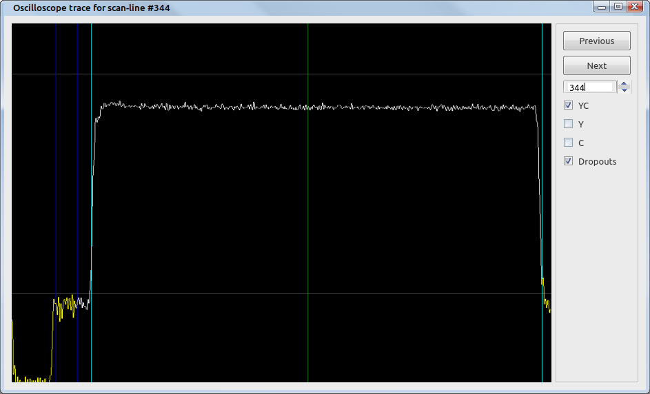
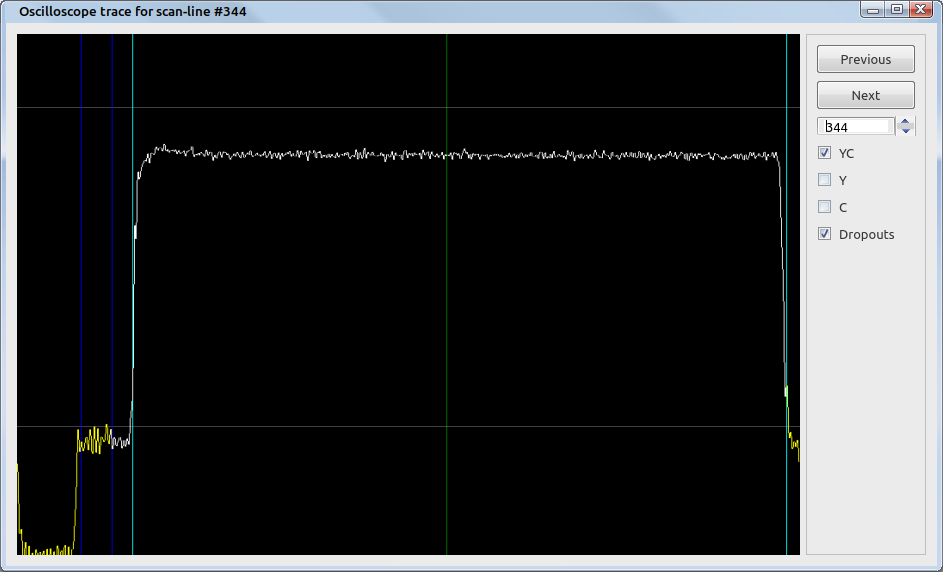
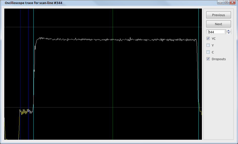
Thanks. I'm still trying to work out the crosshatch pattern. Unfortunately I wasn't able to remove it completely, likely due to the chroma signal on the Sony being significantly higher in amplitude. This signal may be boosted on the RF backend of the player for good color reproduction. The good news though is the capture from the Sony machine is definitely cleaner than the Philips one, and I was able to reduce the crosstalk by using my modified capture card with a 50 ohm terminator over the stock Blackbird card. Take a look at one of the scan lines for the white flash from Tom & Jerry:
Philips machine, 13MHz LPF, 37dB SNR:
Sony machine, 13MHz LPF, 39dB SNR:
Sony machine, 5MHz LPF, 42dB SNR:
Spectrum from this Sony player with 5MHz filter at gain level 15, good noise floor:
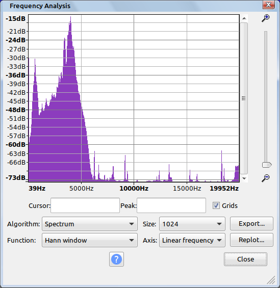
I'm not concerned about the diamond/crosshatch pattern at this point. In fact this may be a better reproduction of the actual tape vs. the Philips player that did not exhibit this, as this appears to be an inherent limitation in the VHS specification. These threads demonstrate the same issue on physical decoding circuits of VCRs:
https://forum.videohelp.com/threads/293921-Diamond-Noise-Pattern-VHS
https://forum.videohelp.com/threads/267778-S-Video-capture-produces-crosshatch-noise
http://www.digitalfaq.com/forum/video-capture/11770-checkerboard-pattern-vhs.html
Looking at the above spectrum, the chroma signal at 629KHz is just too close to the luma signal by design. I'm not sure what can be done in software de-emphasis wise to try and wrangle out the noise, if anything. It's pretty minor for me at this point, and I'd say most VCRs do enough filtering to where it's not noticeable on playback. JVC couldn't push the chroma carrier down further, as it would exhibit too much color bleed. They couldn't push it above the luma signal either due to bandwidth limitations. So like broadcast, the color has to sit somewhere in the middle which creates artifacting. So it's good to see the software accurately demonstrating this limitation of the format as the traditional capture method has done. I imagine the S-VHS format does not have this issue as the luma signal is higher in the band and farther away from the chroma signal.Last edited by Titan_91; 12th Jul 2021 at 13:19.
-
Popping in here with another question. I recently got a VCR that has a BNC output. JVC SR-MV45. Would it work with (insert compatible device here) or do I still need to do a mod? What other devices could I use with this minus the DD? Something about Conexant CX2388x chips? Not sure. I know it's still highly experimental right now but I'm just curious.
-
There is at least few issues.
Your low pass filter may introduce phase distortions - analog filters usually has non-linear phase response and non-flat group delay - it can be important for video to not introduce such distortions - check https://en.wikipedia.org/wiki/Bessel_filter - it should provide lowest phase distortions at a cost of relatively poor gain slope - 50dB filter as yours is or elliptic (Cauer) or at least Chebyshev i.e. gain is good but phase distortions and group delay not.
As VCR use FM modulation then SNR is important for FM demodulator but most FM demodulators are happy when SNR is higher than 26dB so pushing this above 40dB may introduce some issues and don't provide expected results.
Consumer equipment use 75 ohm impedance, professional RF GHz range equipment use 50 ohm impedance, if some signals are extracted from VCR they may be unable to cope neither with 75ohm nor 50 ohm equipment - some active buffer need to be used to match hundreds ohm impedance (common on PCB with integrated circuits) with low cable impedance.
It should be avoided to mix 50 ohm and 75 ohm equipment as BNC connectors are mechanically incompatible ( http://www.cctvinstitute.com.br/bnc-75-or-50-ohms.html ) 50 ohm BNC connectors inner pin is thicker and will damage 75 ohm receptacle. RCA (Cinch) connectors impedance is usually not specified at all (so they may be 75ohm but, for sure not 50 ohm and usually impedance can be 60 or 70 or 90 or any ohm).
It is better to increase RF signal level so it can be matched with expected level at your capture card (so additional benefits from using active buffer - amplifier) - in general FM modulated signal is passed to demodulator after limiter (limiter clip signal to more or less same level so sine is turned to rectangle, with this process also unwanted AM modulation is removed). -
-
-
For the sake of discussion, I found this:
https://groups.google.com/g/rec.video/c/PS3-QOHLajoFor recording, the NTSC luma in VHS systems is frequency modulated onto a
carrier centered at about 4 MHz, with the sync tip at 3.4 Mhz and the peak
white at 4.4 MHz, for a total deviation of 1 MHz. Of course, side bands are
produced which extend well beyond this range and contain a lot of useful
picture information. Care has to be taken to keep the lower luminance sideband
comparatively free of the "downconverted" (heterodyned) chroma upper sideband
which reaches out to 1.13 MHz from its center at 629 KHz. To this end a High
Pass Filter with a frequency cutoff (i.e. -3 dB attenuation) of 1.4 MHz was
typically used in older VHS machines.
In SVHS systems the luminance carrier has a deviation of 1.6 MHz, with a
sync tip of 5.4 MHz and peak white of 7 MHz.
I mentioned earlier that the Sony machine seems to capture more luma bandwidth from the same tape than my Philips. Using the same source material, the Sony's FM envelope seems fatter/wider on the spectrum. That could explain the sharper picture. However, at the cost of that checkerboard pattern showing up, assuming vhs-decode is picking up that wider lower luma sideband and getting into the upper sideband of the chroma signal. There's a chroma gain adjustment in the ld-chroma-decoder portion of the NTSC video generator script. I'll try lowering that to see if it helps. But the above quote seems to explain it pretty well.Last edited by Titan_91; 12th Jul 2021 at 14:52.
-
Lowering the chroma gain didn't work. Using a denoise filter does quite a bit to hide the artifacts though.
-
chroma gain is directly linked with amplitude (level) of the chrominance subcarier - every composite decoder use this (chroma burst) as level reference, similarly black level for luminance is acquired from back porch (place just after chroma burst) - no need to guess with thees simple rules.
-
-
Adjusting chroma gain in ld-chroma-decoder won't have any impact on the luma, the chroma and luma signals are separate at that point. The chroma signal is bandpass-filtered out from the full signal in vhs-decode and then upconverted as in a VCR, and decoded separately.
-
For tape recording chroma frequency is shifted or by heterodyne or by digital divider (like for example dividing FM frequency by 8 so shifting 3.58/4.43) to sub 1MHz range, chroma burst is important for color demod - phase relations (coded color) is in reference to chroma burst phase where phase is fixed (NTSC) or switched (PAL)...
-
Looking at my Philips captures again, the checkerboarding was always there and I guess I just didn't notice it? The Sony captures, even at gain level 1, have less overall background noise in the image. May be due to the gain on the card not being maxed out like is needed with my Philips VCR. I know none of this testing is ideal or scientific (low pass filters have phase delay, no buffers, impedance mismatches in some cases), but since the checkerboard artifact seems to be prominent (also with unmodified VCRs with normal composite output) I'm thinking the root cause it just the VHS standard. On the composite output of my Sony machine the artifact isn't visible at all. But that's probably due to noise filtering or extra processing of the signal. I'm guessing the band between the yellow box and the blue box is the issue:
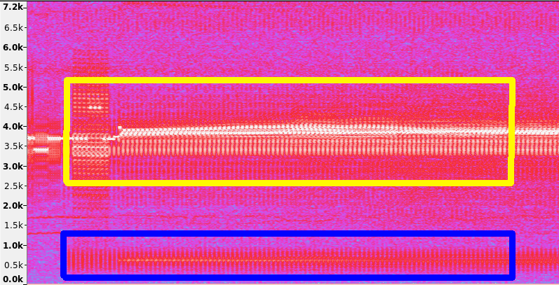
Looking at formats.py, band pass for luma appears to be from 2.6MHz to 5.3MHz so that's where I drew the yellow box. And chroma may have the ability to creep up to 1.3MHz, assuming what I quoted before is reliable. If all that is accurate, then I fail to see how the band between luma and chroma (used for HiFi) can possibly cause checkerboarding in the demodulated luma signal. Unless those boxes are actually much wider, due to filters having gradual "cut-offs" with some deviation allowed for that. Which I could tweak in formats.py to further play around with assuming I'm barking up the right tree.Last edited by Titan_91; 13th Jul 2021 at 21:23.
-
Yep - I understand how colour-under systems work - (heterodyne for VHS PAL/NTSC QAM subcarrier systems and ME-SECAM FM, frequency division for the non-ME-SECAM SECAM FM subcarrier). However I have some recollection that post-heterodyne/division subcarrier processing there is some additional VHS-specific processing of the heterodyned/divided burst for the recorded signal on tape (which is what vas-decode is based around processing). (There is also some additional phase processing isn't there because of the lack of guard-band between tracks on VHS)?
All of this is from hazy recollections of reading service manuals for my VCRs in the 80s. -
Of course there is plenty of equalization, premphasis and deemphasis (worse they are quite frequently adaptive so not static) stages in Y and C path to deal with tape frequency characteristic and overall signal processing implications. My remark was related to Chroma gain and way how composite color decoder AGC act (reference points to set AGC). Luckily for us there are datasheets for VCR video signal processor where frequently not only basic parameters are described but also theory of work and oscilograms provided.
Tracks on VHS should not overlap as tape is constantly in motion and video track relatively narrow when compared to tape/drum speed. -
The "cut-off"/corner frequency for filters are normally specified as the point where the amplitude is -3dB, i.e half. The shape and such depends on the type and order of the filter, in this case it's butterworth filters. At the moment the rf is band-pass filtered with the frequencies you noted. Additionally there's a sharper high and low pass filter at a lower/higher frequency. Adding to that the high_boost stuff boosts the frequencies around max white by picking out those frequencies from a copy of the signal (using a backwards/forwards filter. i.e filtfilt in numpy, to reduce phase distortion) multiplies them with the current high_boost value and adds them to the original signal to reduce missed zero crossings on sharp transitions.
I've been playing around with a peaking EQ filter (amplifying most at a specified frequency) to try to emulate the filtering in a VCR more closely, but I don't really have a good reference to try to correct to. If anyone is knowledgeable about translating analog filters into the digital domain and digital signal processing any help is appreciated. -
Wasn't the point about VHS that it got rid of guard bands and used alternating head azimuth to mitigate and allow video tracks without a guard band and thus right next to each other on-tape.
Philips VCR (NV1500/1700 etc) and UMatic standards had guard bands, but VHS got rid of them and used head azimuth - and ISTR it also used some chroma phase tricks to reduce interference between tracks (as even with great tracking, with no guard bands you will get some 'leakage' of signal from neighbouring tracks if you don't have a guard band between them?)
My point wrt to your original point was that I have memories that you couldn't use the chroma burst amplitude in colour under to set picture subcarrier reference in quite the same way because ISTR that the burst was modified (you can still use it for that purpose potentially - but the relationship between burst and picture levels may be different to composite). Totally agree about black level/blanking reference (give or take the +7.5IRE in NTSC-M) being set in porch. -
Not sure about NTSC (9living in Europe and never get access to real, true only NTSC VCR), PAL switching chroma reference phase each line so in theory some of errors can be nullified (but only to some point like some static offset not dynamic) - in VCR signal processors obviously correct sequence and phase must be restored based on information recorded on tape - as such there must deterministic mechanism supporting this. It was way easier in 90's to get more technical details than today but still manual chroma gain adjustment seem to be inappropriate and it looks like last resort, desperate action.
-
Yep - VCRs will have managed that - but remember VHS-decode is using off-tape RF captures before the replay processing applied by a VCR, and without some of the information that a VCR would have had access to to implement such a deterministic mechanism. VHS decode has to come close to fully simulating what a VCR did with the colour-under subcarrier. After all the chroma isn't part of a composite signal at this point and if the burst:information relative amplitudes have been altered during recording, changing the chroma gain in vhs-decode may actually be the right thing to do.
I totally agree that finding 70s and 80s documentation online is way more difficult than it was when you could get paper manuals back in the day. -
I think I can safely say that using a higher gain level on the card is better than a lower gain level. Higher gain seems to give a cleaner picture, crosshatching aside. Though bringing the gain up will help reproduce a better representation of the signal with the 10 bits we have, it can also raise the noise floor of your CX card if overdone. For me, I've pretty much reached the endgame on the hardware capture side and am ready to start preserving home videos and more uncommon screener promos. This endeavor is kind of a race against time to preserve all the information from the tapes that's possible before the magnetic recordings fade away. Once that happens, any method of preservation becomes impossible and precious memories are lost.
I agree that physical VCRs must be doing something to better separate luma and chroma than what vhs-decode can currently achieve. And the checkerboarding artifact may in fact be chroma gain related. The reason I say this is Brad's tests have varying degrees of checkerboarding using the same tape and different VCRs. Same PC, capture card, cables, and vhs-decode settings. If one VCR is better at recovering the chroma signal from the tape than another, that would likely result in different levels of gain. This may correspond with different intensities of the checkerboard pattern. I'm saying this hypothetically with no evidence of an actual connection, just a hunch.Last edited by Titan_91; 15th Jul 2021 at 20:25.
Similar Threads
-
what is current "best" file uploading/sharing service?
By hydra3333 in forum Newbie / General discussionsReplies: 15Last Post: 30th Aug 2015, 04:39 -
How i can encode audio of "REMUX" to "BluRay.720p.DTS" wit handbrake?
By VideoHelp4Ever in forum Blu-ray RippingReplies: 1Last Post: 2nd Jul 2015, 12:41 -
[SOLVED] "--ipratio" "--pbratio"+"--scenecut" "--minkeyint" / "--keyint
By Kdmeizk in forum Video ConversionReplies: 14Last Post: 21st Jun 2015, 08:21 -
[Help] Problems with the "Title Button" in the "VTS ROOT" and "VTS Normal"
By kirous in forum Authoring (DVD)Replies: 8Last Post: 1st Nov 2014, 13:31 -
How to convert "Still Image" to "AVC file" (like as Godzilla Blu ray Menu)
By ningnong132 in forum Video ConversionReplies: 2Last Post: 8th Sep 2014, 05:23


 Quote
Quote
