


@Oln The conventional capture looked more natural than the VHS decode, The VHSdecode colors are washed out and has less contrast.
+ Reply to Thread
Results 421 to 450 of 1200
-
Capturing Memories

- Jan 2016
- Member Since 2005, Re-joined in 2016


-
What type of capture is preferred? 10bit or high bandwidth?
-
High bandwidth I would say. Someone made a chart which shows the noise floor differences between 8bit and 10bit. It makes no difference in the result, and don't forget many software defined radios run at 8bit as well. For your LimeSDR Mini, you could use something like a Ham It Up to up convert the frequency into something tunable.
-
Audiovisual Manipulator

- Dec 2019
-
9954tony#2102 from Discord said that:Originally Posted by uff
Also 10bit mode causes for me much less problems like constant sample dropping in "double bandwidth" 8bit mode and I'm willing to use it currently (tenbit=1 tenxfsc=1 17,89MHz). Plus it makes easier to pipe the cxadc output to other tools.In 8bit mode, the cx card is still getting 10bits from the ADC, but just discarding the 2 LSBs. So, in reality, those extra 2 bits might not get you much.
Every ADC system has a "real" and "effective" number of bits. Depending on the noise in the system, the ENOB (effective number of bits) can vary.
This is a DD capture i downloaded from IA. It is a noisy disc. I de interleaved the 16 bit sample (discarding 8 bits, keeping 8 bits) and then decoded both.
You can see the results are "virtually" identically (i say virtually, because if you zoom way way in, there is like a 1% difference).
The comparison i talked about before, was the IA GGV disc. That disc was better, so the ENOB on that capture was more than 8, the comparative decodes were 2db apart.
[Attachment 57078 - Click to enlarge]
Often it seems that the perception is that when running in 8bit mode, the cx card is an 8bit ADC.
It isn't, it is a 10bit ADC with the ENOB capped at 8. And there is a distinction there.
An 8bit ADC would have an ENOB less than 8. In LD/VHS, it would probably be around 6.5 ENOB.
I'm not sure if it's driver problem but I guess.
To decode 10bit captures with VHS-Decode you need to use --10cxadc with tenxfsc=0 or --10cxadc3 with tenxfsc=1 switch,
name your input file to have correct extension if it's not compressed: .u16, .r16, .wav,
or compressed: .vhs, .ldf, .raw.oga and .flac.
To record default audio input, cxadc samples and immediately reduce size of them in 10bit mode you can use the following command:
^ Install once if you do not have these packages.Code:sudo apt install sox flac -y
Or without compression if we are worried about single-threaded flac encoder that can bottleneck and cause sample drops:Code:sox -r 48000 -b 24 -c 2 -d capture.wav | sox -r 48000 -b 16 -c 1 -e unsigned -t raw /dev/cxadc0 -t raw - | flac --fast -16 --sample-rate=48000 --sign=unsigned --channels=1 --endian=little --bps=16 --blocksize=65535 --lax -f - -o capture.vhs
I discourage to use dd command to read samples from /dev/cxadc0 - this program is using some buffering that causes to drop data, it's normally used to copy hard drives or partitions but not streams, problem appears even on uncompressed NTFS formatted NVME storage.Code:sox -r 48000 -b 24 -c 2 -d capture.wav | cat /dev/cxadc0 > capture.r16
To reduce size of conventional line input audio and raw video after recording run this command:
From looking at reduced file sizes it seems that flac encoder takes into account fake 16bit file and effectively reduces the size to around the size of 10bit data or less.Code:flac --best --sample-rate=48000 --sign=unsigned --channels=1 --endian=little --bps=16 --blocksize=65535 --lax -f capture.r16 -o capture.vhs | flac --best capture.wav -f -o capture.flac
To solve the problem of weak chroma I use --chroma-gain argument in the chroma decoder:
1.9 from eyeballing seems to be the most correct value when I tried to match the 75% color bars from test generator but if old recording seems to be too oversaturated I use 1.8.Code:ld-chroma-decoder -f pal2d --input-json capture.tbc.json capture_chroma.tbc capture_chroma.rgb --chroma-gain 1.9 | ld-chroma-decoder -f mono capture.tbc capture.rgb
Notice that now single .tbc.json file is used for both luminance and chrominance .tbc files on newest commit to reduce mess, remember to use --input-json argument for color. -
Running at 28.6MSPS 8-bit mode with gain at level 1 on my Asus "Blackbird" card, I did two samples. One without an additional low pass filter, and another with a 13MHz low pass filter inline between the amplifier and input to the card. For these two examples, I'm using a different tape, a Tom and Jerry home video release screener. I changed tapes due to well defined lines and solid colors being used, since it's animation. This makes it easier to analyze noise. This is using the OPA657 broadband amplifier tapped directly to the VCR's RF test point, adjusted as high as possible without losing the output signal. If I adjust it up further, some sort of cutoff circuit in the amplifer kicks in and I lose the signal.
This first example, without the separate low pass filter, has an SNR rating of 26 according to ld-analyse. Considerably worse than the 32 I was getting on the previous tape I was using. I also set the luma filter lower cutoff frequency to 2.4MHz and upper cutoff to 4.8MHz.
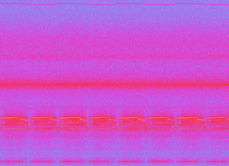
I don't have a decode screenshot of this sample, but it looked like the below sample, just with more of that squiggly noise.
Next, with the 13MHz low pass filter added:
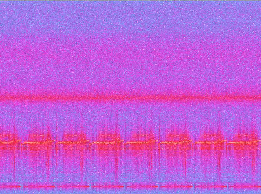
The filter improves some noise in the upper band above the luma FM signal. There also appears to be a modulated head switch signal up near 14MHz the filter cleaned up. In this second sample, the SNR improved to 28.
On this tape and only this tape, there's heavy ringing/streaking on the right side of the image. I hooked up the composite output to my TV and am not seeing this artifact. So this is generated by vhs-decode. There are also some dots below the vertical blanking interval on this tape and overlayed text that can help oln troubleshoot the issue. The sample is attached.Last edited by Titan_91; 31st Jan 2021 at 13:43.
-
Thanks for your detailed response. I will use the 8-bit mode then, since I don't have any issues with dropped samples.
My capture setup is older PC with PCI -> Gigabit Ethernet -> Network Share on my main PC with way more storage. The VCR is connected via an S-Video Port I glued onto there (I desoldered that from a dead capture card). The test point goes to a DC filter cap and then to the luma of the port. An S-Video cable then connects the modded in port straight into my capture card. The audio outs of the VCR gets recorded the classic way in parallel to the cxadc capture. My reasoning for this is that not all tapes have HiFi audio and the regular linear audio would have to be captured extra anyway. Also, the VCR is intelligent enough to switch between HiFi and linear audio on the fly when there are dropouts.
With this setup I can archive lots of tapes and then later on process them on my faster Ryzen and also easily unplug everything when not needed. My goal is to dump my entire collection of old family videos and similar stuff of value to me.
A thing I worry about are all of these "Chroma signal clipping" warnings. Can I just ignore them or does that affect the picture quality if not circumvented somehow?
Also, I'd really like to help with this project, but, while I know Python and how to code properly, I have pretty much no knowledge about signal processing and all the math behind it. So, while I could maybe fix some simple bugs or create a better UI, I can't really help with the stuff that actually matters right now.Last edited by uff; 31st Jan 2021 at 15:22.
-
One thing I would really love to see is a composite video/CVBS implementation of some sort, regardless of who writes it. Maybe fork the ld-decode repository and name the fork cvbs-decode. Then modify the Python script to instead read a captured composite video signal instead of a multiplexed RF signal from LaserDisc or VHS. I imagine it wouldn't be difficult to strip out the filtering, detection, and demodulation code and simply adapt the ld-decode script to output a tbc and json file. That way you can take advantage of the existing mature and fantastic time base correction, luma decoding, and chroma decoding code used in ld-chroma-decoder which already expects a 3.58MHz chroma signal anyway. Or maybe even implement vhs-decode dropout correction.Originally Posted by uff
A lot can be done with that especially outside the scope of LD and VHS, and I would be more than happy to use cvbs-decode or something like it to compare and give feedback on hardware decodes with composite outputs of my equipment. In other words, having that ability could benefit the LD and VHS software decoding side by letting us compare, without having to result to consumer capture cards or devices, which don't support sampling the raw composite video output of the players.
That type of solution would be similar to production formats like D2, which stored digitally sampled 4x subcarrier. Heck, that may even open the door to D2 tape decoding and other digital composite sources! "D2 was an uncompressed format that digitized the composite waveform. The video sampling rate was 14.3 MHz at 8 bits. The data rate was 131.7 MB/sec."
https://www.youtube.com/watch?v=cFacR9M6oXALast edited by Titan_91; 31st Jan 2021 at 16:30.
-
In vhsdecode/process.py line 1362, demodblock() function.
There is a normally disabled code, that plots the CVBS signal in time domain for debugging.
Simply change that 'if False:' with 'if True:' to see the plot.
That video_out variable has the CVBS time series signal.
I agree to have a cvbs_decode tool and/or a Y + CbCr decode tool to get rid of the CVBS color encoding and its comb filter issues.
I mean, something that can decode a more like S-Video signal where luma and chroma are already separated, like in almost all video tape formats.
Currently, there is no automatic amplitude adjustment of the Y signal.
All the recordings I saw have some differences between the sync level, and the black level.
The filters were set by trial and error, and some leveraged with the information found on documents.
IFB, on discord provided the bode plots for the U-Matic PB-Y filters measured from the real thing.
I'm wrapping my head around to get an IIR filter analogue for that plots.
Doing that could solve the filters trial-error issue, or at least, give us the same behaviour as the real machine filters.
There is some ringing in all filters (both in software and hardware), and there is some harmonic distortion caused by non linear amplitude response.
Both can cause ghosting on hard brightness transitions.
But look!, We're getting closer and closer.
-
I'm not sure what you mean, does that output another file with the demodulated CVBS signal? Doesn't the resulting tbc file already have that in 16-bit format? Or plotting as in a graph?
-
I think that is the CVBS signal previous to the TBC.
It only plots like an oscilloscope and pass that information to the next steps.
It don't save it as a file AFAIK.
But it is an interesting place of the code to dump/inject CVBS for testing. -
I wonder if I can take an 8-bit CVBS capture, resample to 16 bits with the correct rate, and replace the tbc file with that? I don't think it will work, as the json file has information about fields, etc. generated during demodulation and that file is needed. "Inject" is the word I was actually looking for, yeah. Just start running the script on the CVBS sample following the demodulation phase before the time base corrector. Then let the script handle the rest from there like it does now. Not sure how hard that will be to do in Python, but I imagine it's trivial just to test the concept. If it works and we can get good results down the toolchain (with ld-chroma-decoder, ld-analyse, etc.) then someone can fork the ld-decode project. I'd do it myself, but I don't know Python. uff and oln do, however, if there is enough interest.
Some other potential applications could include drone racing video, other analog wireless video applications, and retro game consoles (Genesis jail bars issue).Last edited by Titan_91; 31st Jan 2021 at 21:06.
-
I might try that when I got the time. CVBS decoder with software TBC sounds like a useful thing. And CVBS isn't too complex.
By the way, my latest capture had the chroma noticable shifted to the left, is that something the filters could also fix? I'm also pretty sure the Chroma was fine on a different recording though, which is weird. It might have been caused by some clipping on the cxadc. Is it safe to just always record at a lower gain that's known not clipping? If the video is FM anyway, it shouldn't matter that much as long as it's distingushable enough from the noise floor, right?
Even worse, another cassette with family videos had a lot of vsync issues, with vhs-decode shifting the image up and back down. The JVC had no issue with that. Does the TBC not implement proper vertical syncing yet?
Another project I'm thinking of is an AI-based post processing solution designed for analog video tape recordings. Basically, a neural network trained to transform images. The training data would actually be pretty easy to get by just writing digital videos to different tapes and then comparing both. This could also be used for deinterlacing.Last edited by uff; 1st Feb 2021 at 12:16.
-
I have varying results in the vertical blanking area of my captures as well. Not sure if it's because of differences in machines, or the source not strictly adhering to the VHS specification in that regard.
I'll get some test patterns together and upload a CVBS sample captured at the standard 28.6/8-bit rate so we have a reference signal. I have a cheap VGA adapter that outputs the source as 480i, so hopefully that doesn't introduce any artifacting. To ensure best fit, I'll use a 31KHz 480p VGA resolution. -
I decided to use the 240p Test Suite running in 480i mode on my Wii, as it has many pixel perfect test modes. The console also has a very clean video output. The first sample has test patterns, the second has test images. Rename the .zip file to .tar.gz, as the forum doesn't recognize the tar/gzip extension. Or else all you'll get is the unzipped tar file instead of the 2 sample files.
My card does some DC bias adjustment between scenes, resulting in some ramps. That may be correctable in software though, but not sure the ld-decode tools are currently designed to handle it.Last edited by Titan_91; 1st Feb 2021 at 21:46.
-
With the current default band-pass filter settings it looks quite a lot better, lowering the upper cutoff to 4.8 mhz cuts off too much of the uppper sideband I think. Though, the current settings are not ideal either at the moment. It may be better to use a 1st order filter for the bandpass and adjust the cutoffs accordingly instead like how PAL works.Originally Posted by Titan_91
I think the chroma clipping warnings are just due to there being some spikes in the chroma signal and may not have any noticeable impact, but I will investigate, as it happens a lot.
Yeah a CVBS decoder also has it's uses. The demodblock function is where the demodulation happens, so for CVBS you would need to skip the demodulation functions in there. -
Interesting, let me try decoding the Tom and Jerry sample again with your default filter settings. I'll also get a CVBS capture of that same section of the tape. For now, I can sort of decode the luma using Avisynth's rawsource function to get a general idea of how they look side by side.
-
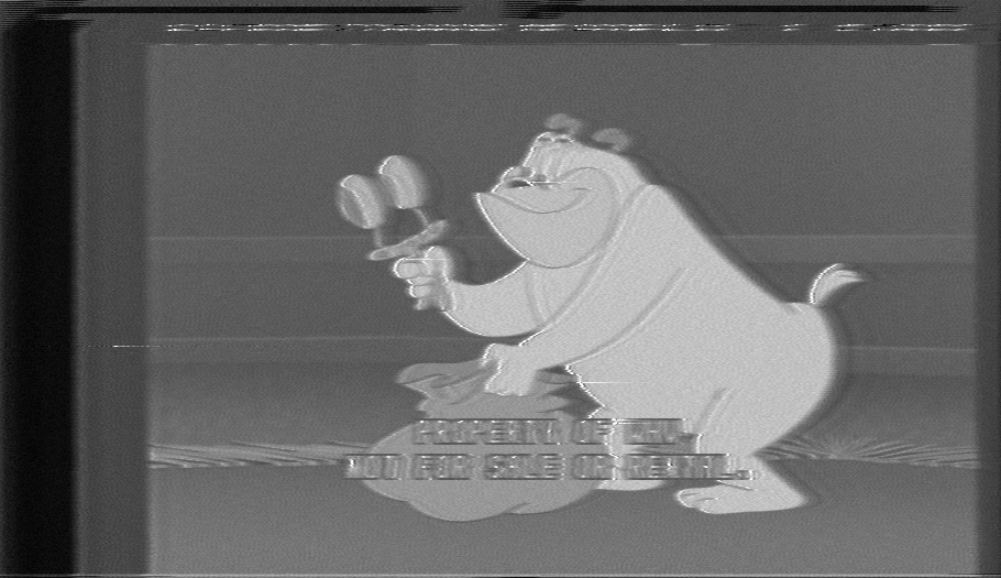
Frame of raw RF capture with oln's NTSC filter settings:

Avisynth rawsource plugin view of NTSC composite video field taken from my VCR's CVBS output:
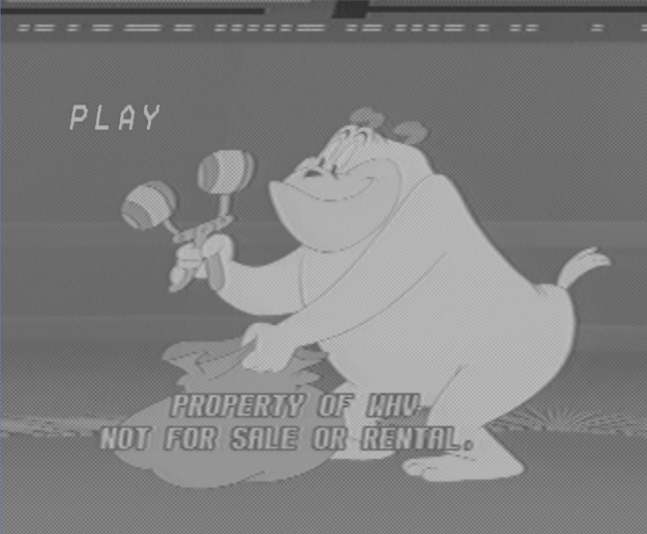
The RCA connection composite result from my cheap VCR is surprisingly good, along with its TBC output. We are definitely getting there! Attached is the Tom and Jerry CVBS sample as well. This time it's a real zip file, since there's no reason to use tar then gzip for a single sample. So don't rename the extension.Last edited by Titan_91; 2nd Feb 2021 at 21:02.
-
For the CVBS decoder: I probably can't find enough time to do that in the near future, so it would be better is someone else implements that.
Is vhs-decode not multithreaded? It takes the same amount of time regardless of the number of threads.
Also, the latest commit gives me a numpy warning followed by a lot of dropping field errors. Maybe this is related to the vertical shift encountered with this tape? I will provide samples and the proper log later. The JVC had no issues with that tape for the full runtime. I think there was a sudden "wow" in the linear audio recording, which might be the motor of the VCR slowing down significantly for a short period of time.
Also, since the VHS signal is FM, wouldn't time base errors result in a shift in carrier frequency? Is the TBC of vhs-decode based on that or does it just TBC the decoded CVBS? I will check it out myself later, but for now I'm too busy with other stuff.Last edited by uff; 3rd Feb 2021 at 07:54.
-
Capturing Memories
- Jan 2016
- Member Since 2005, Re-joined in 2016
-
What's the purpose of CVBS capture? Isn't that what a conventional capture card does anyway?
-
Being able to do TBC in software, which capture cards usually don't do on their own
-
Yes, and no. Typical consumer capture devices have their own decoding circuitry which not only capture the signal in a bitmap image format, they also compress the resulting image causing distortions. Plus, none of this is software based decoding of the analog signal. By capturing the composite output, I'm bypassing all the encoding of a capture box, or decoding a digital TV performs. If we then feed the raw signal into ld-decode, we can use all the existing code to decode and display all components of the signal in software. The only thing the VCR is doing in this case is tracking, demodulating, and up mixing the color signal. The actual conversion to a digital image can be done in software.
Because of this we can cross reference a real machine's output signal to the output of vhs-decode, which is aiming to match the level of image quality of a physical VCR/TV/consumer capture card or box.Last edited by Titan_91; 3rd Feb 2021 at 14:13.
-
Capturing Memories
- Jan 2016
- Member Since 2005, Re-joined in 2016
-
I see the point, but wouldn't be much better to use that effort on TBCing the S-Video output instead of noisy composite? At least we can have a solution for capturing V8 and Hi8 from camcorders since this format is not part of the VHSdecode, I know it can be done but I don't think it's a priority for now. Tinkering with miniature components is no fun.Originally Posted by uff
-
I agree about capturing s-video so the signals don't have to be combined, but most VCRs including mine don't have an s-video output. An S-VHS machine should cover that though.
-
Here's an album that shows each stage. To answer uff's question, the TBC kicks in after demodulation.
https://imgur.com/a/7VNff -
I wonder what would be needed to just skip that and pass the CVBS data to the time base corrector. Commenting out the function doesn't work because I can't code.Originally Posted by oln
-
Capturing Memories
- Jan 2016
- Member Since 2005, Re-joined in 2016
-
Any S-Video source should do the trick but I can contribute with a Hi8 camcorder if I find one on eBay and send it to one of you guys who live in the US.Originally Posted by Titan_91
-
For S-Video you would need some way of capturing both signals at the same time in sync, neither the cxadc or domesday duplicator is capable of that at the moment. I don't know whether it's possible with the cxadc cards, and the DdD would need hardware changes to have more than one high-speed input.
As far as I know the video format on 8mm tapes isn't massively different to VHS, so it wouldn't take a lot of changes to add support for it. The basic principles are the same with all the common color under formats. There are some smaller differences like using phase inversion instead of phase rotation on the downconverted chroma, and possibly some extra filter on the Y channel. I think Hi8 like SVHS may have use some extra Y filtering but I haven't looked at the specs in detail. -
Capturing Memories
- Jan 2016
- Member Since 2005, Re-joined in 2016
-
I didn't say 8mm/Hi8 is different from VHS/S-VHS in terms of video signal, The problem is the players themselves, VHS players are readily available and easy to work on but 8mm/Hi8 decks are in the range of $1000-$2000 so that requires the use of camcorders which are a pain to tap into, at least for the average person if this project would go public, So that's my idea of applying TBC on S-Video for now for that format. But I see your point about Y/C being a dual signal and requires a different setup.
-
I added issue #617 to ld-decode hoping this will get some attention. It will also open up the possibility of software decoding really weird obscure formats where the players cannot be easily RF tapped. Having universal composite decoding, even though it's not s-video, would open up all sorts of doors.Originally Posted by dellsam34
https://github.com/happycube/ld-decode/issues/617Last edited by Titan_91; 7th Feb 2021 at 13:14.
-
PM sent.Originally Posted by VideoMem
 Quote
Quote
Similar Threads
-
what is current "best" file uploading/sharing service?
By hydra3333 in forum Newbie / General discussionsReplies: 15Last Post: 30th Aug 2015, 03:39 -
How i can encode audio of "REMUX" to "BluRay.720p.DTS" wit handbrake?
By VideoHelp4Ever in forum Blu-ray RippingReplies: 1Last Post: 2nd Jul 2015, 11:41 -
[SOLVED] "--ipratio" "--pbratio"+"--scenecut" "--minkeyint" / "--keyint
By Kdmeizk in forum Video ConversionReplies: 14Last Post: 21st Jun 2015, 07:21 -
[Help] Problems with the "Title Button" in the "VTS ROOT" and "VTS Normal"
By kirous in forum Authoring (DVD)Replies: 8Last Post: 1st Nov 2014, 12:31 -
How to convert "Still Image" to "AVC file" (like as Godzilla Blu ray Menu)
By ningnong132 in forum Video ConversionReplies: 2Last Post: 8th Sep 2014, 04:23