


Here the chrominance path in the NV-HD100.
I choose that schematic because it has no so integrated blocks, the NV-FS200 has a M52083 for all the chroma demodulation.
I think it is a form of non linear distortion, or something else. It seems to be at near integer frequency distance from the FM carrier to the downconverted chroma carrier, but in the high frequency side.Originally Posted by Titan_91
The JVC reference mentions something about Fo + 2Fdc
Maybe in this case is something Fo + nFdc being n an integer +- 1/2
The recent SPICE simulation of the luma filter for the PAL panasonic shows a cutoff notch filter around 8MHz (the dB scale is confusing, it depicts it as two notches, but it is a bandpass centered at Fo with asymmetric transition bands)
It might be a strong image of the sync pulses at 2Fo (tomorrow I will tune gnuradio to that frequency to hear what it sounds like. If there was an image of the sync pulses we can hear them) It is not sync pulses related, it is something else.
Maybe the NTSC one has this cutoff around 7MHz.
The Wikipedia article is right for ideal square waves with infinite harmonics, real square waves have not infinite harmonics since physical propagation/transmission/recording mediums have not infinite bandwidth.
Any waveform on time can be expressed as a sum of sine cosine waves:
https://en.wikipedia.org/wiki/Square_wave#Fourier_analysis
By the third harmonic it start to look as an square wave.
Take a look a this video, for me it is a lot better than complementary to the wikipedia and textbooks for undestanding Fourier's work.
https://www.youtube.com/watch?v=r6sGWTCMz2k
The same channel have a lot of other interesting videos on the subject. (Not so easy one to wrap the head around, I'm still trying to catch its full potential)
I found interesting the fact that constant complex multiplication changes phase (it rotates the signal on the complex plane).
I finally understood why they choose the complex numbers to work with instead of let say R², it is all about math notation convenience.
I like to call them stereo numbers now.
Try StreamFab Downloader and download from Netflix, Amazon, Youtube! Or Try DVDFab and copy Blu-rays! or rip iTunes movies!
+ Reply to Thread
Results 331 to 360 of 1043
Thread
-
Last edited by VideoMem; 14th Oct 2020 at 14:20.
-
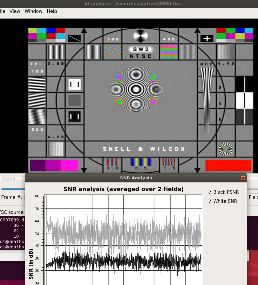
I want to go back to this post and ask a question. Looking at your NTSC video spectrum compared to VHS RF, you illustrate the VHS luma signal going higher than 5MHz. I'm looking to get a better capture card with a lower noise floor. Due to the Carson formula, do you think removing the stock 5MHz LPF designed for video and adding an 8MHz LPF would recover more bandwidth for luma? I've been working with someone on the LaserDisc Database forums who has done the same thing but with a 13MHz filter for LaserDisc. This combined with a well performing card gives superb results with SNR exceeding 40db, even rivaling the Domesday Duplicator solution at under $50 in parts.Originally Posted by VideoMem
https://forum.lddb.com/viewtopic.php?p=117035#p117035
The above example is using a 10MHz inline BNC LPF, but he has done another test with a 13MHz Mini-Circuits LPF with even better results. This most closely matches the 13.2MHz filter design of the Domesday Duplicator.
Last edited by Titan_91; 17th Oct 2020 at 14:11.
-
According to the PAL-B multiburst test capture posted by Zcooger there is very little picture information above 4.3MHzOriginally Posted by Titan_91
By the simulations of the Panasonic NV-FS200, PAL VTR active luminance filter spotted by oln, the zero gain point is at 8MHz, and then, it opens again leaving about 10% of the frequencies above it.
Here are better plots of the SP and LP mode filter bandwidth (linear scale):
An 8MHz LPF instead the default 5MHz one can improve the sharpness of the picture.
However there are some issues with the setup I see on the pictures.
Driving a moderate length coax/BNC directly from the RF test point is not the best impedance match, it can cause some oddness/noise/attenuation.
The head amplifier is intended to drive an unbalanced high impedance line over short distances (PCB traces), I guess it expects a 120/300 Ohms line, not the 75/50 Ohms coax.
(One or) A pair of RF balun transformers can solve the line driver / cable issue, however in the case of the added RGB amplifier/buffer near the testpoint this might not be necessary.
The balun will also help to break ground loop type noise coming from the PC to the player and vice-versa.
I mean something like this:
RF Testpoint -> (0.1~1µF polyester/NPO/ceramic if DC present) -> balun -> coax -> 8MHz LPF filter -> capture card ADC
OR:
RF capture point -> (0.1~1µF polyester/NPO/ceramic if DC present) -> balun -> coax -> amplifier type (A) (with a separate power supply) -> coax -> 8MHz LPF filter -> capture card ADC
RF capture point -> amplifier type (B) (shared supply with the head amp) -> balun -> coax -> 8MHz LPF filter -> capture card ADC
With amplifier (A) I mean one of the channels of the RGB amp.
The (B) one is the one transistor alike solution posted above.
Nice! That's the way. Once this is done we can integrate all the hardware accessories in a PCB and quote it on JLCPCB or somewhere else. I guess it would be around that overall monetary cost.Originally Posted by Titan_91
I've done some progress this days. I successfully decoded luma and displayed it in gnuradio. Here is the screenshot:
There is no ld-decode code involved at all here, so, there is no Sync, nor deinterlacing, TBC or dropout compensation (yet).
I'm currently writting an OOT module for Sync and TBC, since I can't figure out easily how to do proper sync and variable resampling using the modules provided by default in gnuradio.
Here is what it starts to look.
Last edited by VideoMem; 15th Oct 2020 at 16:01.
-
I think I understand. But how can an 8MHz filter improve the picture if the peak of the luma signal is 4.3MHz or 4.4MHz? Does the extra 3MHz of headroom allow for an upper sideband? Your graphs illustrate the notch at 8MHz you discovered when building that actual LPF circuit from a real VCR.Originally Posted by VideoMem
Interesting, never thought about that. I had planned to remove my VGA preamp in favor of a separate LNA because I thought it could be contributing to noise, but I will leave it installed. I used the minimum length of well shielded VGA cable needed to connect the test point to the preamp, using the blue wire of the VGA cable.Originally Posted by VideoMem
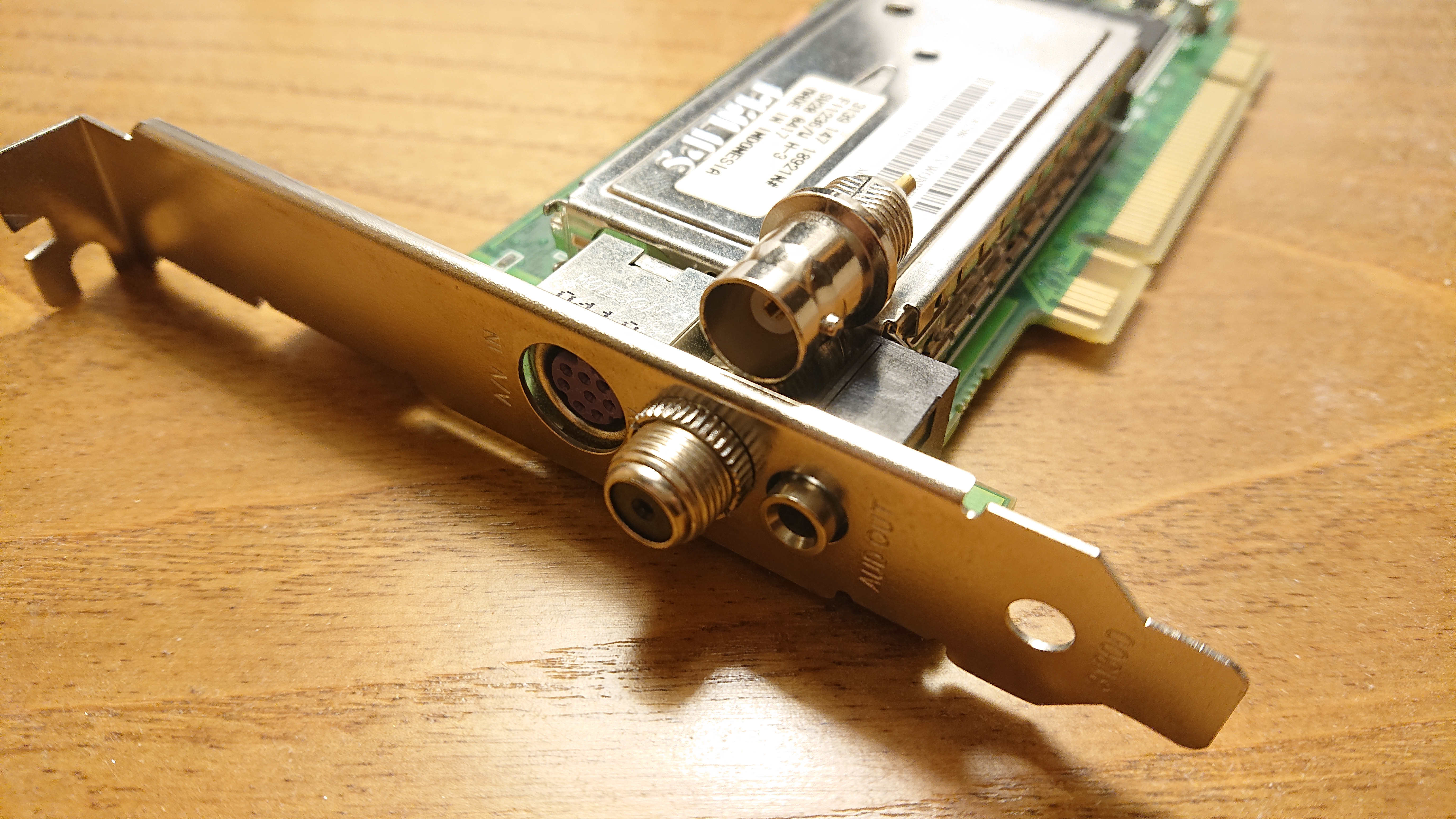
That option is closest to what I have now. The only differences are I have no DC blocking capacitor and no balun. I have ordered these two cards as they are nearly identical to one another and the closest I could find to Tony's well performing card. I plan on adding a 13MHz filter to one for LD and an 8MHz filter to the other for VHS. I only paid $21 shipped for both.Originally Posted by VideoMem
https://www.ebay.com/itm/ATI-TV-Wonder-Pro-PCI-Philips-F11236-W-H-3-MPEG-2-1-TV-Tuner-...d/124387082687
https://www.ebay.com/itm/ATI-TV-Wonder-Pro-PCI-Philips-FQ1238-W-H-5-1029520500-TV-Tune...pid=1328442541
Funny you should mention that. While looking for data sheets I came across this CX23885 listing. These chips, surprisingly, are still in stock by the hundreds ready to order. All that would need to be done is to design and build a custom card/board around the chip with ideal filters, DC removal, BNC input, and other needed frontend stuff. Conexant stressed manufacturers to "take care" when building their solutions around the chip to allow the chip to function at maximum performance. Asus did not take care with the card I have, packing it full of dual tuners, miscellaneous ICs, and input jacks. The other 2 cards I have on order are much less densely packed and I can actually tap my RG174 in to them manually.Originally Posted by VideoMem
https://www.jotrin.com/product/parts/CX23885_15Z
Here's the data sheet illustrating the PCI bus interface. PCI is not ideal though, I wonder if this can be adapted for use with single lane (1x) PCI-E? Or even USB 3.0? This would require modification of the driver though. At the moment it's still easy enough to find older PCs and motherboards with PCI on eBay for cheap.
https://www.digchip.com/datasheets/parts/datasheet/103/CX23883-pdf.phpLast edited by Titan_91; 16th Oct 2020 at 12:27.
-
Would have to look in more detail, but I think the delay line in the lower left is for color noise reduction, the trimpots is for adjusting gain and phase of it. The ones in the upper right are probably involved in NTSC 4.43/PAL60 and maybe mesecam playback and possibly comb filtering when recording. It may be used in normal playback too, I'm not sure. The manual has a simplified block diagram which makes it a bit easier to see what does what, the version at freeservicemanuals.info is much better quality, only reason I linked the other one is that it was missing the head amp schematic.Originally Posted by VideoMem
RF filter/eq is also interesting, it's something I've found very little documentation on. The book I have and techical manuals describe demodulation of the signal using a double limiter, integrator etc, but don't really say much about how the signal is filtered before that other than there usually being a FM agc. The filter setup must be rather crucial though, I don't have the NV-HD100, but I do have it's big brother the SVHS NV-HS1000, and it doesn't take much altering of the SP Q/LP Q trimpots for black or white (depending on direction) streaks to show up, especially on more worn/lower output tapes. If I move the lowpass filter up much in vhs-decode from what it is currently, which is much lower than 8 mhz I also get streaks, so maybe there is more to it we're not seeing here, or maybe it should be higher up and sharper.
As for capturing the signal, personally I used a Sony SLV-SE60. It looks like it already has a 0.01 uf dc blocking cap for the RF test point, I used an oscilloscope probe both with the cxadc card and domesday duplicator, I don't know if that could cause problem or if it's a reasonable way of doing things. The domesday duplicator was designed to tap rf from laserdisc players and is set up for 50 ohm impedance I think. (Also I found later that the VCR had some over-aged power supply capacitors, which I have fixed later, so I don't know if they had any impact on the captured signal, it's been a while since I did the captures.)
I'm tinkering with dropout compensation in vhs-decode now, you can see this dropout quite clearly on the rf waveform:
[Attachment 55530 - Click to enlarge]
Blue is rf, red is demodulated, and green is signal envelope.Last edited by oln; 16th Oct 2020 at 10:35.
-
Yeah the full datasheets for most of the Video ICs don't seem to be easily available. There is one for a slightly newer panasonic one here. Not sure what VCR it was used in.Originally Posted by VideoMem
There are full datasheets for several of the Sanyo ones, like the mentioned LA71750 used in many late-model VCRs made by LG, Samsung, Daewoo, Funai etc, LA71598HM and others.
Also found some for two of the philips chips used in the NV-HD panasonic models, TDA9715 and TDA9725. (I wonder why they used philips chips and not panasonic's own.) -
Has anyone been able to find out what impedence the PB FM test point on a typical VCR seems to be? For LaserDisc it's between 47 and 50 ohms. Zcooger has used 75 ohm coax with good results with both PB FM and Hi-Fi test points.
https://www.youtube.com/watch?v=v6bSq3Rhe6Y
https://forum.videohelp.com/threads/394168-Current-status-of-ld-decode-vhs-decode-(tru...10#post2588915 -
Audiovisual Manipulator

- Dec 2019


I think I didn't put this info anywhere but Discord - I used 50Ω coaxial cable (RG-58). I didn't check or tried to match the impedance yet between VCR and PC but I want to know how to do it so the reflections disappear.
-
Your capture on I Love Lucy shows that 7MHz can pass that filter, so I'm doubting now about the 5MHz LPF transition band.Originally Posted by Titan_91
Maybe it has a cutoff at 5MHz but a transition band around 3MHz.
I can't get a link to download/see anything at freeservicemanuals.info. It only shows the first page thumbnail.Originally Posted by oln
Yes, I would have to look it in more detail too. I annotated it with questions, because I was in the search of the "comb filter" thing.
Comb filtering only on recording seems to make sense, because fixed delays with tape playback flutter/jitter will cause oddness (I think)
The oscilloscope probe solution is interesting. I think is one of the best.Originally Posted by oln
Another thing I observed on 'how to detect dropouts' (which is the first step on dropout arbitrage) is the fact the demodulated signal often goes to sync level when in dropout on the display area. It is expected to the signal stay between 0.3 and 1V and not going lower than the black level (0.3V) on the display area section.
I think it could be a way to flag a dropout.
Thinking, maybe that's the reason why they called it 'dropouts', as a reference to something that being drop from some height.
The double limiter thing is a plain rails cut/saturation, lets say, you pass the FM through an AGC that normalizes the signal amplitude to be between 0 and 1V (but it has a gain adjust response about a line time), then you demodulate the FM, then you put a rail block (that's how they call on gnuradio) to ignore all the spikes coming lower than 0V and higher than 1V if the signal goes crazy between hsync pulses.
Here what I see on the demodulated signal when it dropouts:
https://youtu.be/WOioBu-iQ0M
The .grc file:
VTR head RF signal test_PAL_SDL_plain_raw.zip
The names of the tabs are residual from previous tests, the only valid is the Luminance one
Overaged electrolytics are a plague on these machines, and the beta ones, specially late 80s machines.
If it smells like fish, you have bad caps. ( The electrolytic inside the cap has a Pyridine based compound, which smells fishy when leak )
Camcorders suffer for that problem too.
If the leak is not fixed in time, it corrodes the PCB. The machines start to leak when plugged in after been sitting 20 years or so, watch them.
Check this:
https://www.youtube.com/watch?v=g86YG9xdkK0
and
https://www.youtube.com/watch?v=2wenyS4EjY0
This guy has a lot of videos on troubleshooting helical scan tape machines, from U-Matic to DAT.
99% of the time are bad electrolytics in some critical filtering (not everywhere, no need to recap them all)
This video brought me here. He also hacks the players a lot.
I started with the intentions of decoding the PCM-F1 adaptor, then I found it was already done
https://www.youtube.com/watch?v=WMY3sWeCeF0
And this:
https://www.youtube.com/watch?v=araPTKCUdA0
Beta/Umatic seems to record the signal in a similar way.
I never made such measure, but I guess it can be done loading the pin with a fixed resistor and scoping the signal.Originally Posted by Zcooger
Let say, you measure it at no load, and measures 1Vpp
Then you load it with a 120 Ohm resistor and measures X
Then you deduce the internal source thevenin's resistance impedance.
I guess that output impedance can change between amplifier to amplifier IC, it is not an standard.Code:<- this voltage source and Rth are internal to the head amplifier, the goal is to determine Rth +------/\/\/\/\--------+ Rf testpoint | Rth (V) | ---
The circuit I've mentioned for the luma filter buffers the signal coming from the head amplifier prior to sending it to the filter.
So I guess the amplifier might don't have the power to drive a coax directly without hassle, (or at least they take special care in that design to not to load it with anything)
PD: I think USB 2.0 / 3.0 is the way to go, but PCI express can be a good solution too
Ground loops are an issue too, besides the impedance matching, a transformer that separates the ground from the machine and the capture device / RGB amplifier could improve the S/N ratio.Last edited by VideoMem; 17th Oct 2020 at 05:00.
-
What type of balun would you recommend installing between the test point and RGB amp, and how should I solder it in?
-
Something like this (isolator + impedance adaptor?):
https://www.amazon.com/ANHAN-Female-Coaxial-Ground-Isolator/dp/B077TP95PK
And / or this (only impedance adaptor):
https://www.amazon.com/VIMVIP-PAIRS-Video-Balun-Transceiver/dp/B00QUI36AM
I'm not sure if they gonna work. I you ask me, I will experiment winding one on a small ferrite toroid core with magnet wire.
But that enters the electronic craftmanship area.
Not sure if it can be done with already made commercial parts. These ones are the nearest I found.
The second one is the standard 4:1 non ground isolated CCTV balun.
The first one seems to be a 1:1 isolator 50 Ohms to 50 Ohms, but I'm not sure.
A signal generator capable of 3~5 MHz and an oscilloscope can be used to determine the transformer ratio.
The impedance ratio is:
Zp/Zs = (Np/Ns)²
Where Np is the primary turns and Ns the secondary turns, these are direct proportional to the voltage ratios between primary and secondary.
Zp is the primary side impedance, and the Zs is the desired secondary impedance (50 Ohms)
Let say you have a 4:1 turns ratio balun, if you apply a 5MHz @ 1Vpp sinewave to the primary it might produce 250mVpp in the secondary
Then you turns ratio is 4:1 because:
1 / 0.25 = 4
Zp = Zs (Np/Ns)² => Zp = 50 Ohms * ( 4 / 1 )² => 50 * 16 = 800 Ohms
Then it adapts a 800 Ohms line to a 50 Ohms line
A 1:1 isolator is what I think is needed to break the ground loop issue, but it only will work well if the RF testpoint output impedance is already 50 Ohms
The signal at the input of the ADC needs to be 1Vpp (peak to peak), as is present in the testpoint.
A 4:1 will reduce the amplitude to 0.250Vpp, but it will match the impedance of the coax cable.
To use the 4:1 directly the signal must be amplified 4x by a transistor stage and a class B push pull driver amplifier prior to sending it to the impedance ratio matching balun.
And the common ground between primary and secondary present on that devices must be disrupted to prevent the ground loop issue.
For soldering it, place it near to the head amplifier as possible with a twisted pair input soldered to the testpoint (the 800 Ohms side), and then use the coax/BNC output as is for connecting the rest of the chain.
I'm assuming the input impedance of the card / RGB amplifier is 50 Ohms.
If the card already have a programmable (analog) gain frontend, then the amplifier stage prior to the balun is not needed.Last edited by VideoMem; 17th Oct 2020 at 17:12.
-
Would a DC removal capacitor installed in series work for isolating ground as well?
Last edited by Titan_91; 19th Oct 2020 at 21:17.
-
It will decouple the low frequency component of the ground loop noise, but not the MF ~ HF band component.
The signal has picture / machine information from 50Hz to at least Fh * (284-1/4) + Fh/625 for PAL-B,
and 455 * Fh / 2 for NTSC, as I interpret from the JVC reference
Fh = 15.625 kHz (PALB) or 15.734 (NTSC)
It yields 4.43362 MHz for PAL and 3.57949 MHz for NTSC
The capacitive reactance of a capacitor of 10nF (0.01µF) at 1 MHz (yes, 1 MHz) is
XC = 1/(2piFC) = 1 / (2 x 3.141592653 x 1 MHz x 10 nF)
= 15.9 ohms (to 3 significant digits)
Which is comparable to the magnitude impedance of the transmission line.
A 100pF capacitor (estimated stray capacitance between primary and secondary of the balun) have a reactance of about a megohm and half at the same frequency.
I'm not expert on this particular subject, maybe someone who is skilled with the MF ~ HF band of "amateur radio" could help us with the best solution here.
Maybe shango066, MrCarlson from Mr Carlson's lab, Dave from EEVBlog, or CuriousMarc.
(in band frequency order )
)
That band is a mess with SMPS switching noise present in the modern PCs and home appliances.
Even a VCR with an unshielded RF case could incorporate noise to the signal.
Capacitive coupling between the VCR ground and the PC ground is far from ideal, not only for the signal, also for the VTR electronics.
Who could guarantee that the servo controller loop will perform as desired in the presence of a strong ground noise coming from the PCs and surrounding appliances.
These devices have resurrected in an strange atmosphere, that's wasn't present as strong in the days the specs were written.
Could be reflections possible at all with 10 meter wavelength in cables up to 1 meter length?
RF is funky.
Some measurements should be conducted with real equipment.
Maybe besides the picture information specs there is vestigial recording of other things in some parts of the signal.
Teletext as an example beween fields,
NICAM audio? I don't know anything about NICAM audio yet.
A2 Zweikanalton? What?
Macrovision?
Does a capture here have macrovision enabled?
I recently saw a resume of the domesday86 project here:
https://www.youtube.com/watch?v=klK4UZ5nlqs
The whole concept were erased from my head.
I refreshed it. How far we are from that milestone point?
I'm not from UK, USA, Canada, France, Japan or Australia, and I'm far from having the proper equipment to measure things, I don't have access to the machines.
You have them.
Even the internet here is not what it should be for 2020.
I will inspect the captures/write software as far as I can, but I can't experiment with anything physical, the specific knowledge I have from the subject comes from the setting up of experiments, internet, and the introduction from the formal (public) institutional technical education.
This domesday should include:- Analog circuits
- RF frequency issues
- DSP techniques
- Some statistics tools
- Software craftmanship basics
- Electronics craftmanship basics
- Plenty source of raw data
- Plenty source of annotated technical manuals
- Mad scientific method
There are PCIe to regular PCI 32 bit adapters too
There is some other control signals present in the machine that can be logged along with the linear audio as the servo control track.
These are low frequency, maybe a capturing the servo track in one stereo channel and another time reference signal from the machine such as the head switch signal could help to the dejitter part.
Does anyone knows how the vhs-decode / ld-decode does the sync thing?
In the current gnuradio setup I have, I successfully lock the horizontal frequency, but having some trouble with the vertical.
Also, the luma signal present in the recording doesn't have the same timing as the expected in broadcast / CVBS
It seems to miss half scanline between fields.
A second order bandpass over the luma with a start frequency of Fh and an end frequency of Fh*3 does the magic to provide the horizontal reference.
A trigger / level comparator provides the reconstruction.
The same applies to vertical frequency.
For speed sake, I resample the signal to sample_rate/10 prior to sending it to the filter stage.
Something like audio samplerate of 192kHz will also work
Code optimizations?
Sure.
LTO tape seems to have the same width size as in VHS (12.65 mm), I don't know about the formulation, it must have a coercivity between 600 and 800 oersted (for S-VHS).
The thicknes is less in LTO (6.6µm) vs (19 µm) on S-VHS (except E-240).
Fujifilm America still has a section on the web dedicated to the VHS pancake (9 track computer storage medium seems to be tape compatible)
The cassette enclosure and the tape spools could be 3D printed.
The another thing is the heads.
Could hard disk or other type of head be mounted in a custom made device to scan the tape to reconstruct a "magnetic microscopy" image of the recording for further processing?
I made this youtube playlist for this project:
https://www.youtube.com/playlist?list=PLokqWqJnNRq7IjSPMjEzwmoRmapk4zKal
This research is going wild.
The analog format in my country is a variation of PAL, it is called PAL-NC. It not even conforms to the PAL-N specs and it is broadly undocumented.
Last edited by VideoMem; 20th Oct 2020 at 06:33.
-
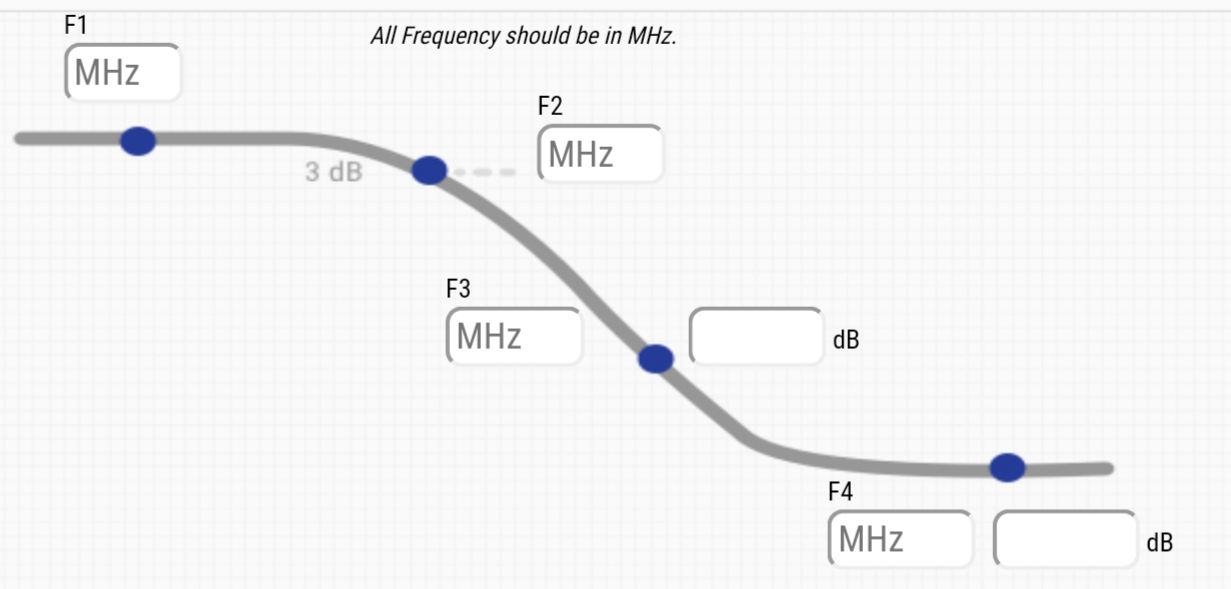
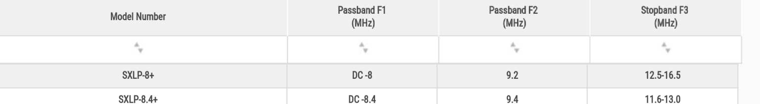
Would this be a good choice for LPF? The pass band ends at F1 8MHz, transition band is F2 9.2MHz, and stop band frequency F3 ranges from 12.5MHz-16.5MHz.
https://www.minicircuits.com/WebStore/dashboard.html?model=SXLP-8%2B
Last edited by Titan_91; 29th Oct 2020 at 08:34.
-
It looks fine to me.
The stop band is a little too near to the Fs/2.
But it could do the trick.
I would try both. -
That filter should get here soon. I also have some female panel mount BNC headers on the way. Will post the results of my modified CX card in the next 2 weeks or so.
Last edited by Titan_91; 5th Nov 2020 at 20:48.
-
I decided to try a 13MHz filter instead, which also from Mini-Circuits. Someone donated one to me for use with Laserdisc captures, figured I'd try it with VHS as well. I should be able to modify my card this weekend with a direct tap to the CX chip. Looking forward to the results!
-
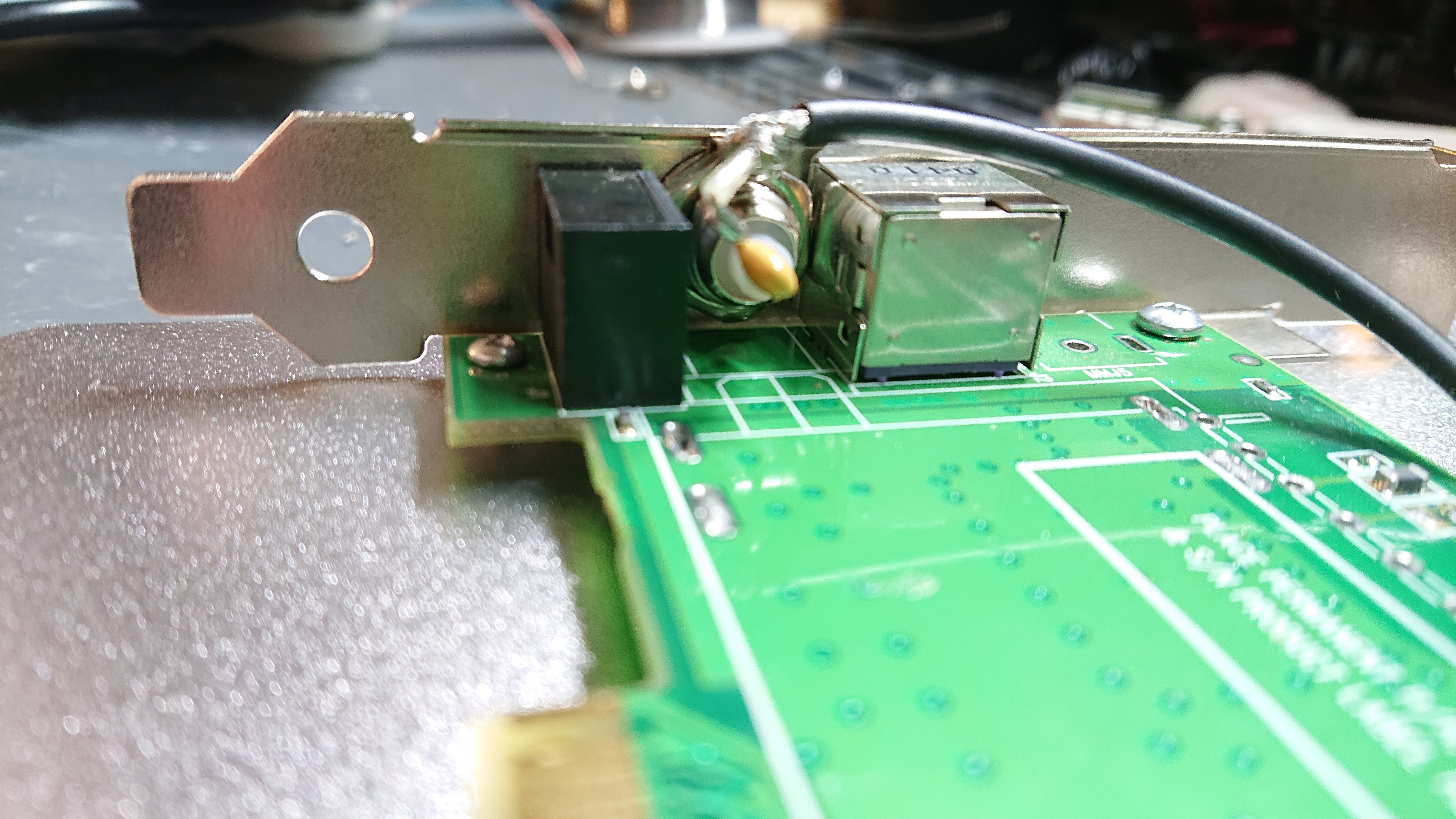
I also noticed, the tuner has a few pins soldered to the board. I decided to remove the tuner and slot my BNC jack in its place.
Last edited by Titan_91; 12th Nov 2020 at 20:16.
-
The mod is done. And it went well! I got some help and we removed the tuner with a desoldering gun. Once that was out of the way I searched for a top side trace for the video output of the tuner, but had no luck. So I stuck with the vmux2 line.
I had access to this awesome surface mount component remover. Taking the 50 ohm resistor off was a 2 second process.
I then tacked on just enough copper to ensure no bridges or shorts.
I then installed the BNC header. The nut fits perfectly. I used a 104 100nf ceramic capacitor in series for DC isolation.
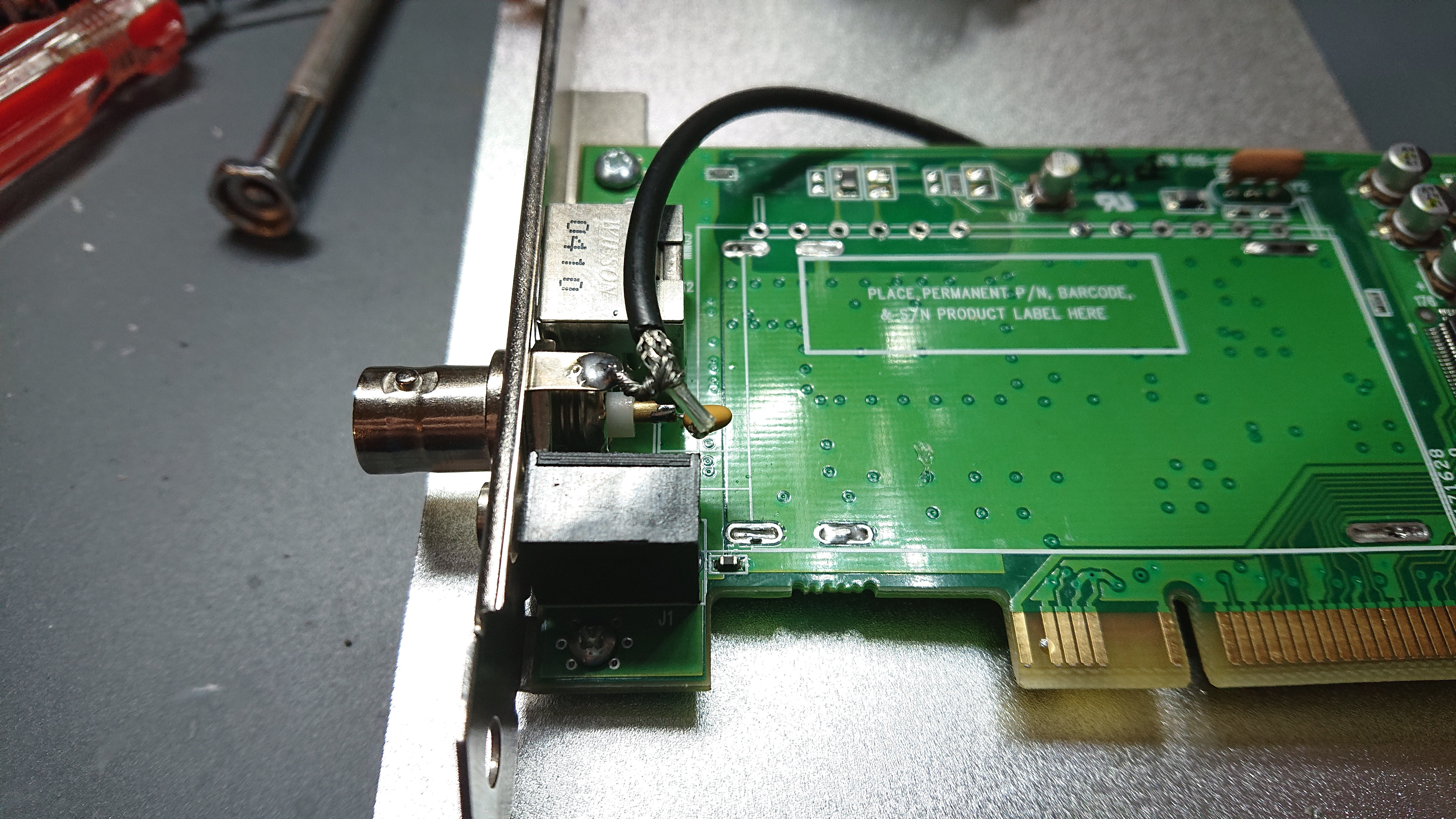
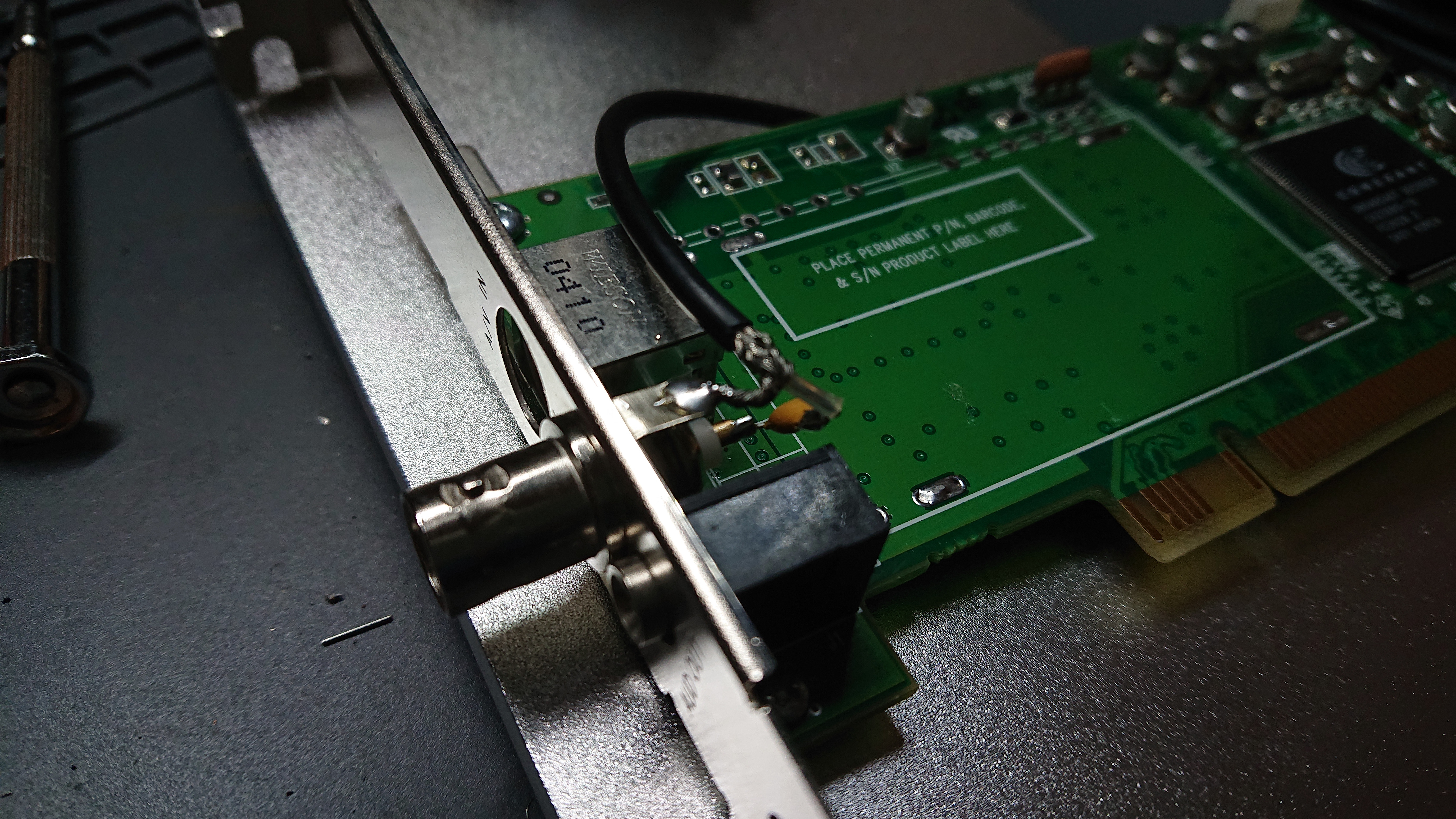
Finally, some low temperature hot glue secures the mod.
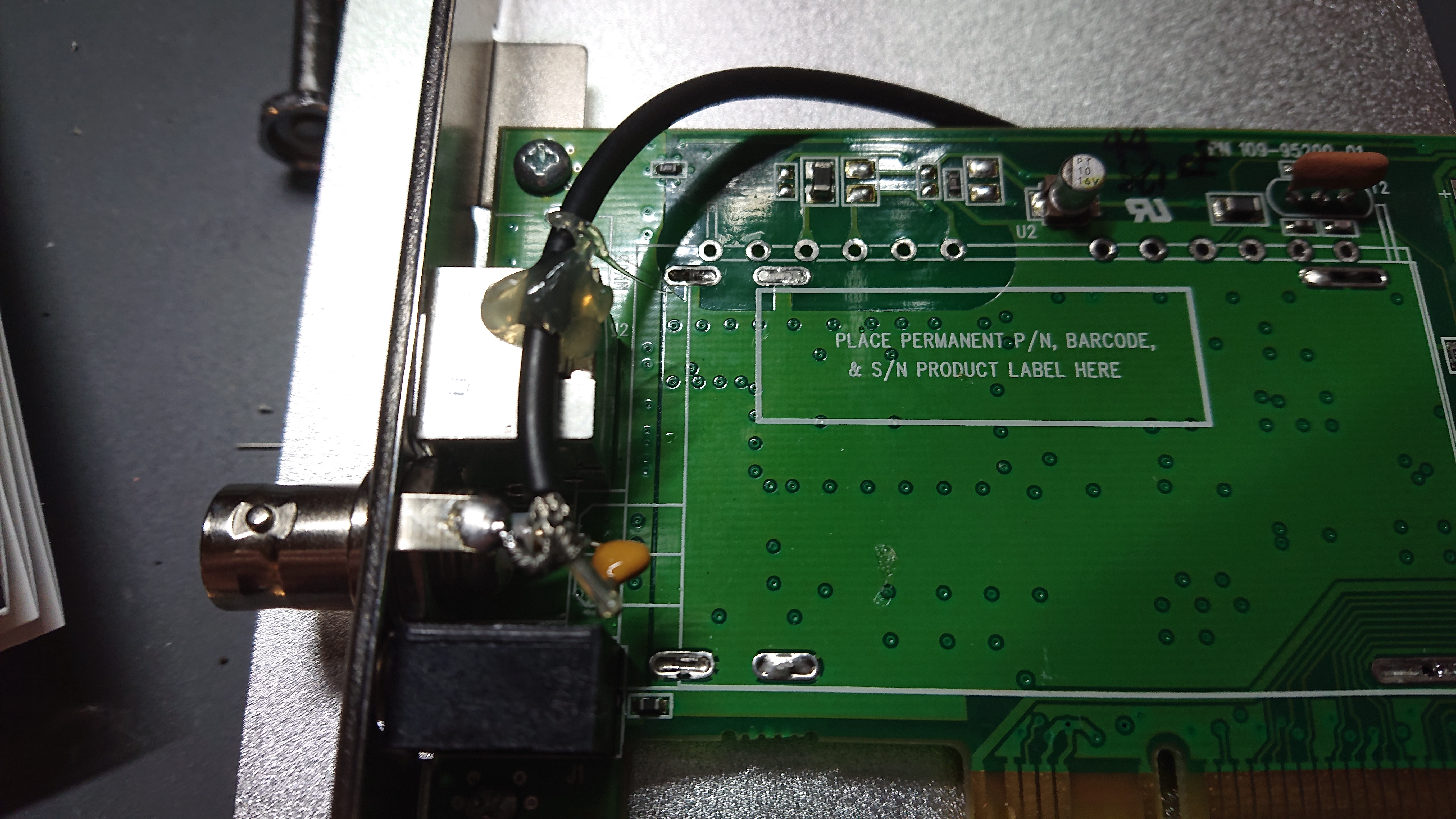
Will test tomorrow. -
Results seem to be better, but it's very close if not a little worse than my stock Asus card. I took 4 captures, and got 3 successful decodes. I had to turn the gain up to 31 again as well. One outstanding plus is the DC blocking capacitor, as expected, has removed the DC offset in my captures caused by the head drum tachometer. Which makes me think, is there insufficient DC blocking on my original Asus card?
Direct feed with no Radio Shack video distribution amp and no low pass filter:
This time with my Radio Shack amp and no low pass filter:
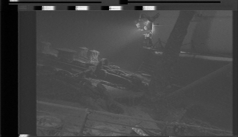
Now with no Radio Shack amp and low pass filter connected:
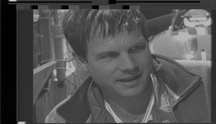
My last capture with the amp and filter both connected failed to decode, so I'll try it again. I think it will look the best out of the 4.
Here's the unmodified Asus card capture I have to beat:
Last edited by Titan_91; 14th Nov 2020 at 16:04.
-
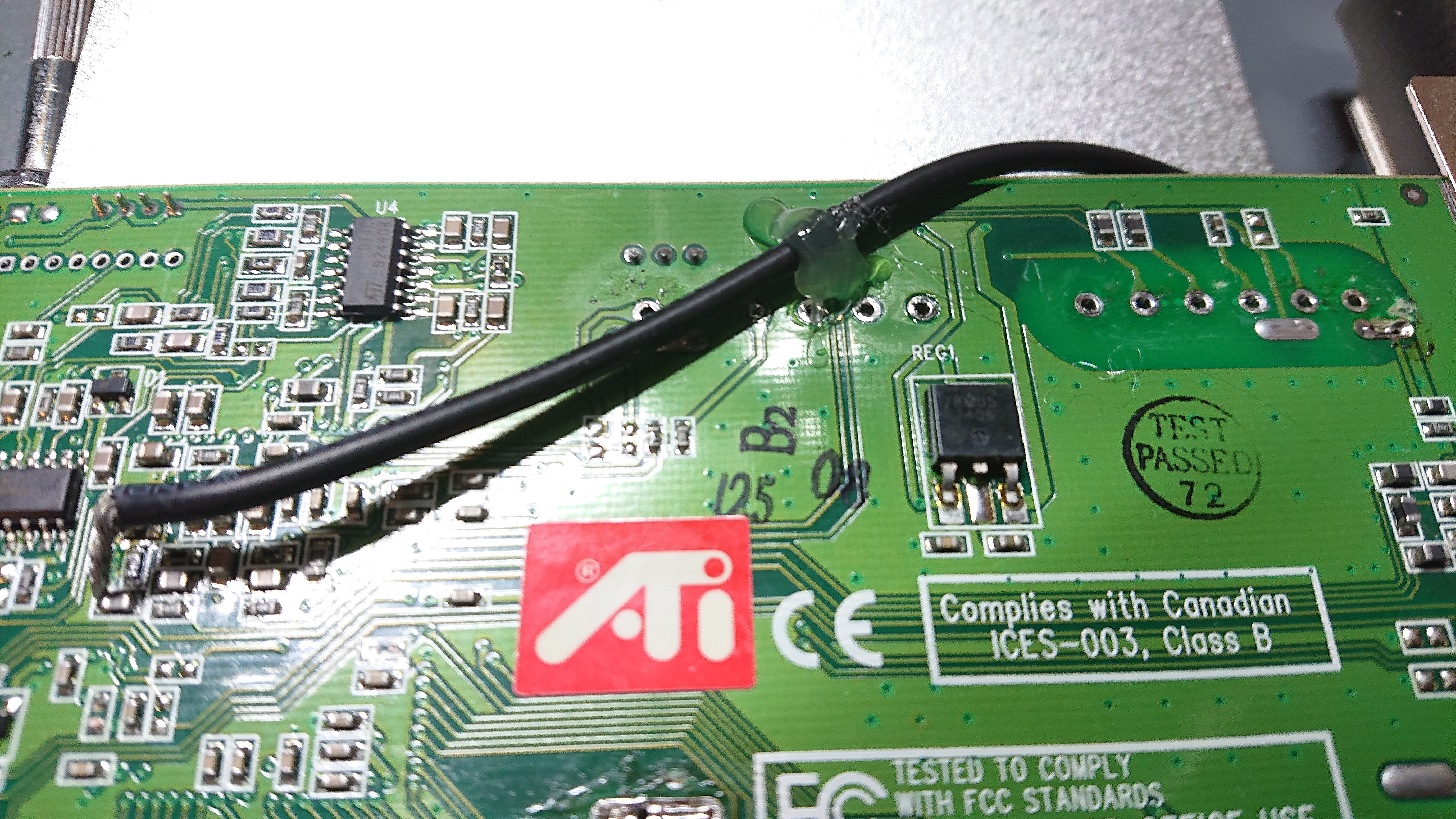
I never got the captures with the amp and filter to decode. There's something about this tape that that causes vhs-decode to lose sync pulses, I think it's the Macrovision. The waveform looked good in Audacity. I made one more change to my card, I cut a trace that was acting as antenna and picking up some pretty bad noise. That is now resolved. The result looks visually the same with and without my 13MHz low pass filter. Still seeing some faint background noise, but I still want to increase the gain of the input signal somehow. Maybe another amp to replace the Radio Shack one. I noticed that one softens the image a bit, reducing horizontal resolution. There's probably a filter in that amp causing that.
Also, I was just made aware the tan colored components are actually capacitors, not resistors. When measuring across them I must have picked up another circuit, which explains why I still got DC continuity with 75 ohms. I'll be removing both of those from the board and testing again to see if my SNR improves. They're probably still acting like 5MHz low pass filters.Last edited by Titan_91; 14th Nov 2020 at 18:51.
-
The decoding failure could be down to a decoder issue rather than your sample, there are still a bunch of kinks to iron out. Looking at the dark/bright transitions on your images I think the signal filtering in vhs-decode is still quite a bit off.
I've not been able to put down too much work lately, but I do have dropout compensation partially working now, what remains for a basic implementation is to automatically determine the rf signal strength threshold used. It's set to a fixed level in the latest commit, but the rf levels will vary between tapes and capture device so it needs to be set based on some average. VCRs may be using the rf agc for this to get a stable reference level but I don't know for sure. -
Thanks for the input. I did adjust the filter lower cutoff frequency a while back, and just haven't set it back to the values you used. It allows me to recover a lot more detail and I can more easily see noise that way, assisting in cleaning up my signal.
Speaking of, while I ruled out the first 2 caps in my signal path, there's a third one I had evidently missed. It's probably still acting as a LPF. I removed it and will test again for more signal on the upper band, which I appear to be missing so far.
-
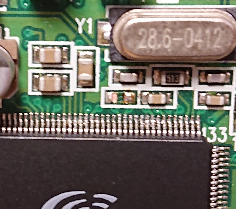
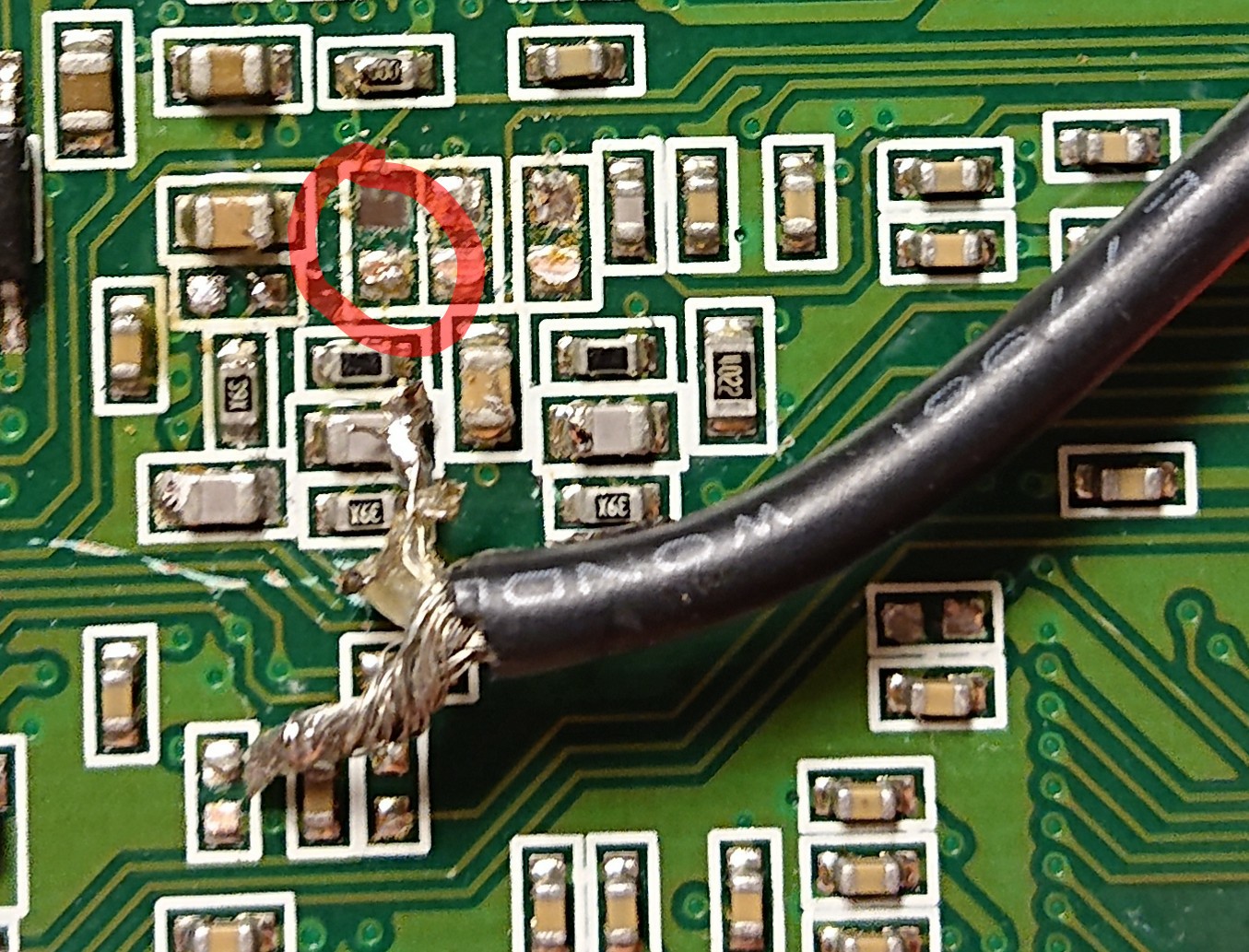
Before testing again, I learned the pin I need is in fact pin 143, and tapping pin 146 was a red herring caused by another path. I found another set of capacitors on the back of the board lined up with these pins and removed them. Unfortunately the pad circled in red going to pin 143 came off the board when I soldered to it. So the plan now is to solder to pin 143 directly from the top of the chip.
-
Latest ntsc_color_broken commit now has basic dropout correction added. It's not turned on by default, but can be enabled by the
option in vhs-decode. Detection is pretty basic for now, and uses either a percentage of the average signal level (defaults are 0.146 for 40 mhz captures and 0.3 for non-40 mhz ones), or can use a set absolute value supplied on the command line. UseCode:--doDOD
to adjust the percentage, or useCode:-D value
to force it to use a specific absolute value. For an absolute value you would have to peek into what the average level of the video envelope is in the specific input file as it will vary wildly between capture setups. One thing I do need to implement at least is some hysteresis, can look into more advanced stuff later.Code:--dod_t_abs value
the .tbc and .tbcc files will have to be ran through ld-dropout-correct to actually replace the pixels with dropouts with something.
[Attachment 55955 - Click to enlarge]
I also added an option to adjust the black/white points in the json output file a little so you avoid the signal being clipped when converting to rgb and set it to do it a little by default. Can be adjusted with.Code:-L value
Lastly I added two bash scripts that run the chroma and dropout correctors on the tbc and tbcc files and merge them files into a ffv1-encoded avi file (made with some help from zcooger). -
Capturing Memories

- Jan 2016
- Member Since 2005, Re-joined in 2016
-
Keep up the good work, Are we close to a final product? The screen shot is 576 lines, Shouldn't be 480 or 486 since it's NTSC?
-
The screen is from a PAL tape to show an example of dropout correction. It works with NTSC captures as well though.
Big thing that's still missing is auto-detecting the track and fixing chroma decoding for NTSC. -
Capturing Memories
- Jan 2016
- Member Since 2005, Re-joined in 2016
-
Is this a DOC result? It looks as good as a VCR one if not better.
-
Yeah it is after running the tbc through ld-dropout-correct with dropout detection enabled in vhs-decode and decoding. ld-dropout-correct can do inter(default) or intra-field compensation. The image is with inter-frame on luma but not on chroma. I don't think the inter-field stuff is all that sofisticated though, but you could in theory use some fancy inpainting algorithm to mask it much better than a VCR. VCRs other than a few broadcast decks can only really repeat the previous line, typically without chroma, so it doesn't take much to do better than a VCR in the digital realm.
Here's the original before masking, and bars showing where dropouts are detected.
[Attachment 55964 - Click to enlarge]
[Attachment 55965 - Click to enlarge]Last edited by oln; 23rd Nov 2020 at 19:23.
 Quote
Quote
Similar Threads
-
what is current "best" file uploading/sharing service?
By hydra3333 in forum Newbie / General discussionsReplies: 15Last Post: 30th Aug 2015, 03:39 -
How i can encode audio of "REMUX" to "BluRay.720p.DTS" wit handbrake?
By VideoHelp4Ever in forum Blu-ray RippingReplies: 1Last Post: 2nd Jul 2015, 11:41 -
[SOLVED] "--ipratio" "--pbratio"+"--scenecut" "--minkeyint" / "--keyint
By Kdmeizk in forum Video ConversionReplies: 14Last Post: 21st Jun 2015, 07:21 -
[Help] Problems with the "Title Button" in the "VTS ROOT" and "VTS Normal"
By kirous in forum Authoring (DVD)Replies: 8Last Post: 1st Nov 2014, 12:31 -
How to convert "Still Image" to "AVC file" (like as Godzilla Blu ray Menu)
By ningnong132 in forum Video ConversionReplies: 2Last Post: 8th Sep 2014, 04:23