


I measured that effect in analog audio compact cassette too.Originally Posted by Zcooger
The high frequency component vanishes with time, but it does that exponentially in the first days after the recording.
It is some kind of naturally occurring low pass.
I guess it happens because at high frequencies the wavelength is comparable with the magnetic particle size, and after a time each particle copies the signal strength of their neighbours causing a blurring effect.
I don't know what exactly does the sharpness knob.
I guess it filters the high frequency band of the luminance with an highpass filter, then amplifies it a couple of dBs, and the sharpness knob is an analog mixer which have the original signal in the low part of the potentiometer, and the original + the amplified output of the high pass (sharpener) in the high part of the potentiometer.
It seem to destroy the colour because in composite, color subcarrier is in the high part of the band, (not exactly the same on tape), adding a strengthened signal from the high pass causes the S/N ratio of the chrominance to deteriorate.
It may add some overshoot artifacts to the hi-band signal confusing the chroma PLL too.
Another thing I found on the video tape recording captures, is ghosting.
That doesn't seem to be compensated in the already made hardware.
If an horizontal completely white line on a black background, cuts on the screen, let's say at half of the screen width. A shadow can be seen in the remaining line, and it may be present in part at the beggining of the next lines in the same field.
Software echo cancelling techniques could be used to correct that.
But first, lets focus on de-jittering, and amplitude compensation.
I'm tempted to write a video vectorscope for the raw RF ( or at least an audio signal generator to use with an audio vectorscope to see an analog version of the relations between color burst, and croma R-Y, B-Y parts of the signal )
If we can see what jitter does on a vectorscope, then I think the best algorithm to choose could be straightforward.
Try StreamFab Downloader and download from Netflix, Amazon, Youtube! Or Try DVDFab and copy Blu-rays!
+ Reply to Thread
Results 301 to 330 of 1060
Thread
-
Last edited by VideoMem; 1st Oct 2020 at 03:57.
-
I think I found something here.
I made wrong assumptions, first, the downconverted chrominance is not FM, it is AM modulated.
I didn't found any chroma information vestige on the luminance (yet), I will dive on this further, as in the book "Video Camcorder Servicing and Technology" attached on this thread mentions CVBS being low pass filtered previously to FM modulation, for recording the luminance information.
... the signal passes via a
low pass filter, which cuts off at 3.38 MHz to filter
out the 4.43 MHz colour signal that may cause
beat patterning with the FM carrier.
Then I found not possible to de-jitter with the luminance FM carrier directly using some reference on the raw luminance RF band, as its carrier varies from 3.8 MHz to 4.8Mhz (at least I don't know how).
A jitter on the tape reading speed causes FM modulation, so the jitter traduces to noise on the demodulated FM signal.
Yes, jitter will cause luminance noise too.
But, as chroma being AM modulated, it is expected that its carrier it is held constant in frequency over time.
Any frequency deviation may indicate jitter.
So...
What if I graph the phase shift between the 629.36 kHz 625 kHz chroma subcarrier and a generated sinewave at this fixed frequency?
I researched GNUradio for how to measure phase shift between two signals (the first building block of a PLL), and I found a method using the FFT block, skip head block, and the keep 1 from N block.
Here is the tool I made for this analysis:
Here is its block diagram:
And its sources:
VTR head RF signal test_chroma phase shift_resample.grc.zip
The red line on the graph is the low frequency of the phase shift component, and the blue the high frequency component.
It changes phase periodically from -pi to pi radians and have some DC bias (maybe due to frequency mismatch?)
The jitter made both signals to swing on DC, and it is present on all the jitter example capture and the older more strong signal captures with "no jitter".
Both signals have a sawtooth shape (the low frequency component and the high one).
It doesn't depend on the image pattern recorded.
All the captures of NTSC examples outputs the same waveforms.
The carrier frequency was misaligned, and maybe it is misaligned on the VTR.
It measures at 559.375kHz 625 kHz instead of 40 * Horizontal Frequency = 629.36 kHz; Fh = 15.734 kHz, specified in the JVC reference for NTSC, in all NTSC captures provided.
Here the phase noise on the chroma carrier (all vhsjittertest.r8). Not .flac this time! Near Gaussian noise doesn't compress at all:
jittertest_Phase_Noise.m4a
Here the tool running as an example, it contains all the previous conversion of the vhsjittertest.r8 capture ( with misaligned frequency )
)
https://youtu.be/p97jJ3n7ptQ
Previous version screenshot (the sawtooth pattern is caused by the frequency misalignment), normally it should look like white noise:
Notes:
For the vectorscope, I found the QT constellation sink, and the Oscilloscope Music Project ( a much nicer one ).
https://oscilloscopemusic.com/osci.php
Here an artistic representation I made while experimenting:
https://youtu.be/wA0uDH62b64
Edit:
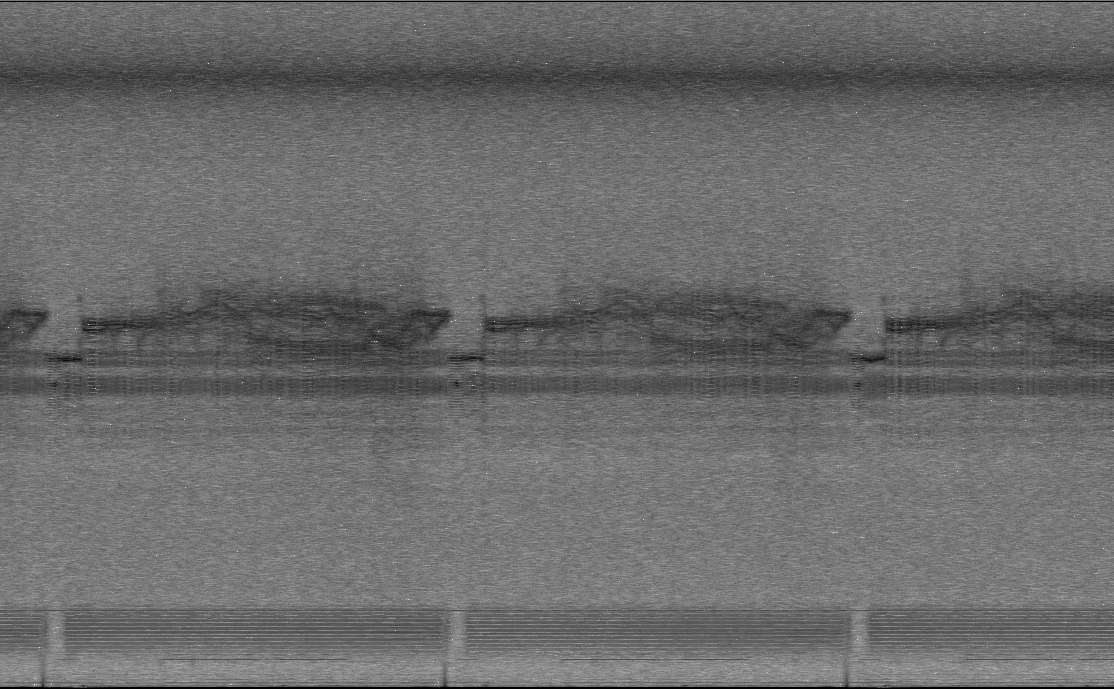
First pattern heavy jitter sectors shown in Audacity
Last edited by VideoMem; 1st Oct 2020 at 18:49.
-
The research on jitter you're conducting is quite interesting. Thanks for all your input so far. Zcooger, did you simply feed a composite signal onto the luma pin of an S-VHS recorder to get it to record the 3.58MHz chroma signal? Or did you have to manually inject that signal at some point in the recording circuit?
-
Capturing Memories

- Jan 2016
- Member Since 2005, Re-joined in 2016


Try this audio file with the Oscilloscopemuic app, It's spooky:Originally Posted by VideoMem
-
Thanks for the feedback!Originally Posted by Titan_91
Nice!Originally Posted by dellsam34
-
I confirm that the head switch drum tachometer signal is present on the RF signal.Originally Posted by oln
For the NTSC captures it is about 30Hz in frequency, square wave shaped high pass filtered.
Something I haven't found yet in the documentation is if the drum rotation speed changes between PAL and NTSC.
I guess it would, as it mentions 25 rotations per second.
So, in NTSC it should be 30 rotations per second.
This is how it looks after DC removal and filtering:
All the jitters on audacity ( the third track is the head switch drum speed signal ):
All the jitters marked:
Wave references:
Phase Shift.wav
Phase Shift_slo.flacLast edited by VideoMem; 4th Oct 2020 at 18:26.
-
How did you determine that signal is for drum speed instead of head switching? And I wonder if the amplitude shift is causing noise in the decode. I kind of doubt it.
-
I'm not really sure, my measures can be wrong.
But I have some clues:
1) By frequency observation, I measured 29.978895 Hz for one complete period of the signal (mean of the measures within 95% confidence interval of 200 measures)
If the machine has two heads, and the drum rotates at 30Hz, I expect 60Hz for the head switch signal (two heads) and 120Hz for 4 head machine.
Unless I measured 1/4 or 1/2 of the real frequency.
2) The documentation shows this:
So I guess the head switch is internally represented by the machine from the drum speed signal ( it multiplies its frequency x2 or x4 and syncs to it )
Meantime I haven't reach the tracking part, maybe in that section it explains it better how the machine syncs the head drum speed to the head switch signal and performs the tracking (I guess it has a variable delay for the head drum rotation syncing).
Here is the first pattern phase shift (the first two tracks) sample rate corrected to be in real time with the third track (head drum speed).
phase_shift_first_pattern_real_time.m4a
Note that the head drum speed frequency is very stable but the chroma phase lags notably during the jitter glitches.
....
I haven't yet reached the vhs-decode chroma part to assert if it has issues by the phase shift (It might, because the colour is QAM and it doesn't sync to the color burst from the luma part, it only uses horizontal sync to TBC)
I'm writting the RF de-jittering part, once completed we would compare it with the raw input. (or discard this assumptions as wrong!)
On the LaserDisc the de-jittering is easier than in the VTRs, because the signal is delta sigma modulated.
Delta sigma modulator have a modulation frequency at least an order of magnitude higher than the maximum frequency on the analog baseband.
Once you sync a PLL to the delta-sigma frequency you have the de-jittering almost done.
On VTRs, the device syncs a PLL to the colour burst of the luma and then it demodulates chroma from the downconverted part, using the PLL frequency as the converter frequency. (plus the discrete phase delay selector synced to the head switch to minimize the crosstalk)
That's the cheaper and 'easier' way of doing that by analog hardware.
The study I'm doing was possible at the time the machines were manufactured to be a consumer product, but the electronics to correct that would be cost prohibitive.
It means that could be another and better solution to decode the signal using the current computing power.
If an FM signal jitters in time (doppler effect on a receiver mounted on high speed moving targets, or this case where the relative speed of the tape and the head can change), and the PLL bandwidth doesn't compensate that. I'm sure it will produce amplitude noise on the demodulator output (luma banding).
Amplitude jitter will not affect the FM part (luma) as much it affects the QAM part (chroma)
For the HI-FI audio part, phase jitter will cause variations in volume, noise, pops and crackles, depending on the severity.
As if this were not enough, there is crosstalk between tracks on the downconverted chroma because its band doesn't benefits too much from the slant recording technique.

Last edited by VideoMem; 4th Oct 2020 at 18:01.
-
Finally some progress here:
NTSC pattern original, frame number 10 (vhs-decode luma as-is):
(region of interest zoomed)
Same frame but first passed through a PLL synced to chroma frequency, and then resampled applying variable delay to the samples proportional to the phase shift measures:
Gamma levels corrected on gimp.
I will update with more details later.
The file:
NTSC_pattern_de-jitter_test.7zLast edited by VideoMem; 5th Oct 2020 at 19:51.
-
That's cool, but to me the before and after screenshots look the same. What am I looking for?
-
Capturing Memories
- Jan 2016
- Member Since 2005, Re-joined in 2016
-
Is that checkerboard pattern is present when playing back the tape normally from the VCR output or in vhs decode capture only?
-
There is a subtle (near unnoticeable) difference on the timming of the signal.
In the original, the gray bar on the left starts its lines with more jitter.
In the 'corrected" version the timming error is less pronounced.
In can be seen on the vertical line on the transition from black to gray.
However. This approach (delaying the samples and dropping) it is only an approximation. And it can be a false positive result.
I'm working on a better solution that involves demodulating all the carriers in gnuradio directly with an stack of PLLs, and then reconstructing the RF signal again without carrier jitter.
Things were going to be convoluted. The diagram is now at least three times bigger than it was in the first tests. ( I need to slice it to smaller functional blocks)
Today I sucessfully decoded the luminance FM. And I'm near to lock onto the phase of the color.
I've been reading the docs and understood how the anti- crosstalk downconverted recording chroma works. It's a bit hacky.
They shift the phase by 90 degree on each line. So, locking a PLL to this carrier without taking this into account will cause undefined behavior and artifacts.
I demodulated the downconverted chroma too and sepatated the B-Y and R-Y components.
I can see a flower type of pattern on the QT constellation vectorscope for the colorbars pattern. But it keeps rotating and doesn't lock yet. (And when the head switchs it explodes all over the display)
Frequency shifting the luma to its baseband FM using a PLL synced to the average of the donconverted chroma phase and then shifting it again to its corresponding frequency by a fixed oscillator seems to have a bit of improvement on the timming.
But I'm black-boxing here the vhs-decode part. It seems to 'prefer' luma on 3.8Mhz. But it also works from 3.6 to 3.9Mhz with different results.
Other things I tried today:
Demodulating the FM to the baseband luma, then applying the de-emphasis of 1.26us, then setting the sync tip and white peak to be a real number in between 0 and 1. Then applying some filtering, and pre emphasis, then hard clipping to rails levels to avoid overmodulation and then FM modulate it again with a 1Mhz of maximum deviation produces a nice cleaner spectrum but vhs -decode complains about sync detection or severe vertical sync corruption.
I can't get any picture but the waveforms and spectrum looks clean and like on specs. Tomorrow I will troubleshoot this.
I will try to generate only sync signals first. -
It's hard to tell. There's definitely some noise in the source signal. I used a cheap VCR to record on what is probably cheap tape. Here are some photos using my Sony PVM monitor. Most are playing, the photo with the scrambling at the bottom is due to the VCR being paused. I would use my LCD TV for this but it's quite terrible at displaying VHS.Originally Posted by dellsam34
https://imgur.com/a/i4sfpz0
I have Robin Williams' The Timekeeper from Disney World in 1995. I have a digitized H.264 copy of my VHS source which was captured with a Hauppauge HD PVR a few years ago. I want to compare results using this example. One, the tape is likely high quality and the camera it was recorded on was quite expensive. So a good source. Two, it's a darker scene which will bring out any noise. Three, it was played back on the same VCR to do the initial capture that I have now modified for raw RF capture.
Obviously, I still have the original video tape. I'll just need to dig it out and rip the H.264 HD PVR version as well. I'll upload the normal video and raw RF sample so we can start comparing noise. It's about 25 minutes long (if it was recorded in one take) so about a 50GB file size. I won't be including the Hi-Fi audio as my machine isn't set up to capture that.
Let's see how well we can decode this one vs. the poor quality YouTube examples!Last edited by Titan_91; 8th Oct 2020 at 21:33.
-
That checkerboard pattern could be the chrominance vestige on the luminance signal.
Some VHS recorders use the plain CBVS signal with a lowpass filter around 3 Mhz (color recording NTSC) as the luminance and it seems to be the case here. If the signal is monochrome with 60Hz VSYNC the device should extend the lowpass to 4.5MHz resulting in a sharper image.
It can be some type of nonlinear tape distortion artifact at Fo + 2Fdc (Fo: FM carrier, Fdc downconverted color signal) that is mentioned on the JVC reference manual on page 14 of the PDF document.
Or it can be some unhandled de- interleaving artifact harmonic of the line offset system.
For the control samples it could be useful to have a monochrome only capture on the colorbars pattern through the CVBS video out setting the saturation to zero on the VCR settings.
I don't know if your VCR have s-video out to capture only the monochrome + sync from the luminance pin.
A multiburst pattern would be helpful too.
It needs to be set at 60 IRE 70 IRE (not 100 IRE) for VTR testing to avoid intermodulation distortion on the FM.
https://web.archive.org/web/20141031003122/http://www1.tek.com/Measurement/cgi-bin/fra...otesting2.html
Tomorrow I will make that testcard if it is not available.
The ones I found on the web are not so good in resolution. (Done)
Some notes regarding to processing the signal on gnuradio.
Don't use the WBFM block to demodulate the luminance FM.
It is intended for audio bandwidth and only the vsync part survives.
( I learned that by the hard way)
The quadrature demodulator block and a lowpass filter works better.
Edit:
Here is the multiburst (4x frame size):
Frequencies: 500 kHz, 1 MHz, 2 Mhz, 3 Mhz, 3.58 Mhz, 4.2 Mhz)
For VTR testing:
Code:$ python3 multiburst_generator.py -s 4
Code:$ python3 multiburst_generator.py -s 4 -c 1
Code:$ python3 multiburst_generator.py -s 4 -c 2
For CRT testing:
Code:$ python3 multiburst_generator.py -s 4 -w 90 -d 1
Code:$ python3 multiburst_generator.py -s 4 -w 90 -d 1 -c 1
Code:$ python3 multiburst_generator.py -s 4 -w 90 -d 1 -c 2
The python 3.x code that generates it:
multiburst_generator_v0.zip
Usage:
It has some bugs when other lines per frame / aspect ratio is specifiedCode:$ python3 multiburst_generator.py -h usage: multiburst_generator.py [-h] [-l [LINES]] [-s [SCALE]] [-d [DEVICE]] [-c [COLOR]] [-a [ASPECT]] [-w [WHITE]] [-b [BLACK]] [-o [OUTPUT]] Generates multiburst testing charts for video bandwidth testing optional arguments: -h, --help show this help message and exit -l [LINES], --lines [LINES] lines per frame (default 525) -s [SCALE], --scale [SCALE] scale of the output image (default 1) -d [DEVICE], --device [DEVICE] target device -> 0: VTR, 1: CRT monitor (default 0) -c [COLOR], --color [COLOR] color pattern -> 0: grayscale, 1: red, 2: blue (default 0) -a [ASPECT], --aspect [ASPECT] aspect ratio (default 1.333333 [4:3]) -w [WHITE], --white [WHITE] white clip level (default 70 IRE) -b [BLACK], --black [BLACK] black clip level (default 10 IRE) -o [OUTPUT], --output [OUTPUT] write to file (default, None)
I will start a github / gitlab public repository for these tools later.Last edited by VideoMem; 9th Oct 2020 at 19:10.
-
I haven't checked on NTSC, but on PAL tapes at least there is some patterning in strong color areas like this on a normal VCR. The internal comb filter/noise reduction usually reduces it quite a bit, it's more visible on a VCR with EDIT mode on. It's likely due to the chroma and luma sidebands overlapping a little. Older often VCRs had a B/W mode which turned off color encoding/decoding and turned off/reduced the chroma parts being filtered out from the luma signal so you got a slight bit more of the lower luma sideband if you didn't need color.Originally Posted by dellsam34
-
My VCR does not have an s-video port for VHS mode, only for use with DVD playback. I also don't have a monochrome mode. I do have some monochrome I Love Lucy material though. I will capture a bit of that.
-
While we're on the subject, someone on the LaserDisc Database forums pointed out various low pass filter capacitors on two different CXADC capture cards were attenuating the captured signal. That NTSC LaserDisc signal goes up to 9.3MHz. NTSC VHS goes up to 4.4MHz. The pass band on these cards seems to drop off around 5MHz for NTSC, and 6MHz for PAL, per the composite video standard of 3.58MHz NTSC chroma and 4.43MHz PAL chroma. My results are much better with VHS SNR wise, due to VHS being 3.4MHz - 4.4MHz. LaserDisc is 7.6 MHz - 9.3MHz.
It was recommended to me to remove the LPF capacitors from my card and use a new 13.2MHz LPF in its place better tuned for LaserDisc. That's 3.9MHz of headroom before the transition to the stop band. But for VHS, does this seem necessary?Last edited by Titan_91; 9th Oct 2020 at 15:11.
-
Removing the low pass filter caps/ redesigning the adc front end could improve the bandwidth response, but it can add aliasing artifacts.
The most demanding in bandwidth is PAL-B. It has from 7 to 8 MHz in channel bandwidth.
It is FM modulated to be recorded on tape with a 1Mhz of maximum deviation centered between 3.8 MHz and 4.8 MHz.
Using the Carson rule to estimate the required bandwidth (BT):
BT= 2(∆f+fm) Hz
where ∆f is 1Mhz (the maximum deviation) and fm is the maximum frequency component of the baseband signal (8Mhz)
It would require a 18 MHz for the complete FM signal bandwidth, plus the shift caused by the modulation it goes above 20Mhz.
If only half sideband is recorded, it yields around 11Mhz which coincides with the someone's observation on the LaserDisc database forum.
At 35.8 MSPS there is not enough samplerate to play around with.
If the filter transition band is lazy as in the case with the analog filters with a non fast frequency roll-off, some harmonic components could appear near to the nyquist frequency causing aliasing and worsening the result.
In the NTSC captures, the highest peak observed is between 7 and 8 MHz with not so good SNR.
I doubt the VHS tape and heads can do something above 9 MHz at all.
S-VHS could
I have not studied the LaserDisc hardware yet.
I guess the maximum frequency is much higher than 9 MHz, as it is delta sigma modulated on the disc.
But you only have to discriminate between 1 and 0 (1 bit ADC).
Does they capture the analog low-pass signal reconstruction directly from the laser photodetector?
You can also cheat the laser disc player to run at lower speed and clock rate, but I don't know if these circuits are available for hacking on the working players, maybe there was on the early players, the ones who have the gas type lasers.
It would scramble all the other circuitry and the analog video output, but at slower rotation speed you could theoretically capture it with a no so high samplerate.
Maybe circuit bending its oscillators to run at half the speed would do the trick.
That's not applicable to the tape, as when you change the speed you change the frequency response of the head.
If the last burst (the one on the right of the multiburst pattern is blurry, the frequency response of the whole system is below 4.2 Mhz)
A recording of these patterns on a good quality tape could be a good measure of the required bandwidth.
Tomorrow i will provide an python oscilloscope + spectrum analyzer to see the luma on the captures. It is a part of my current gnuradio circuit experiment.Last edited by VideoMem; 9th Oct 2020 at 21:47.
-
I've having a new issue with CXADC. I removed my card to check the filters. After putting it back in, Linux is saying the module isn't loaded, yet insmod and mknod work without errors. I haven't updated the kernel or anything else. The card is fully seated in the PCI slot, I checked this twice. I also downloaded and built the current version of CXADC. Here's what in my terminal.
Edit: I fixed it. Either the new driver or something else on my system now requires /etc/udev/rules.d/cxadc.rules to be present from GitHub. I've never even touched this directory before and it was previously empty. I all of a sudden also had this issue with the older CXADC module I've been using for months. So not sure what was going on with that.Code:~/Downloads/cxadc-linux3-master-new$ sudo insmod cxadc.ko vmux=2 tenxfsc=1 level=31 user@mintiplex:~/Downloads/cxadc-linux3-master-new$ sudo mknod /dev/cxadc0 c 126 0 user@mintiplex:~/Downloads/cxadc-linux3-master-new$ sudo dd if=/dev/cxadc0 of=/home/user/Desktop/MonoChromeTest.r8 dd: failed to open '/dev/cxadc0': No such device or address user@mintiplex:~/Downloads/cxadc-linux3-master-new$ ls /dev | grep cxadc0 cxadc0 user@mintiplex:~/Downloads/cxadc-linux3-master-new$ sudo rmmod /dev/cxadc0 rmmod: ERROR: Module cxadc0 is not currently loaded
Last edited by Titan_91; 10th Oct 2020 at 15:28.
-
Other than PAL-M and PAL-60 (which are sort of NTSC with PAL color encoding), the difference between the PAL versions are in how they were broadcasted and fm-encoded (including sound) over the air. The signal on tape and on composite/s-video will be the same, though VCR in different areas would have different tuners to be able to receive and decode the over-the-air broadcast in the area.
PAL VHS has peak luma at 4.8 MHz, the sideband will extend a bit further up, but I'm not sure if the full upper sideband is retained. Here's an example of the RF Luma band-pass filter from a Panasonic NV-HD100 PAL deck (fullmanual) (there's a 100 ohm resistor right after the RF amp before this as well, head amp schematic is missing in the good manual.) if anyone knows a lot about electronics and can deduce an approximate frequency response from it (gray colored line from right to left):
[Attachment 55403 - Click to enlarge]
Looking for something similar for a NTSC one, but service manuals for older models seem more scarce for NTSC models.
The before/after modulation/demodulation the luma signal is normally low-pass filtered at around 3 Mhz on input/output in VCRs for standard VHS, so anything above that in the original signal is not retained.
SVHS is a fair bit higher, peak white is at 7.4 MHz, not sure how far up the sideband extends on the recorded signal. There are differences in what tape formulations are capable of carrying, though SVHS-ET did enable a fair bit more than standard-VHS bandwidth but not quite SVHS on normal VHS tape formulations.Last edited by oln; 10th Oct 2020 at 12:25.
-
VideoMem, I understand your concerns about bandwidth and the Carson formula. However, and I'm far from an expert, but the results we and others have been seeing with the Domesday Duplicator's 13.2MHz low pass filters and 28.6MSPS (capturing up to 14.3MHz) seem to suggest the Carson formula doesn't apply. And here's why I think that is. Each frequency modulated single is modulated by a single base band source signal. IE, stereo audio channels having their own pair FM RF signals, and the video RF signal being modulated by a single CVBS signal. So in this case, yes there are multiple RF carrier signals. But from what I understand that formula only applies to a broad of continuous number of baseband signals modulating a single FM carrier. That doesn't seem to be the case with LaserDisc or VHS, as each of the individual FM carriers are being modulated by a single source signal.
From the Domesday86 site:
"LaserDisc players often employ a filter which has a stop-band of 13.2 MHz (above the upper parts of the video signal) and this design is also used by the Duplicator."
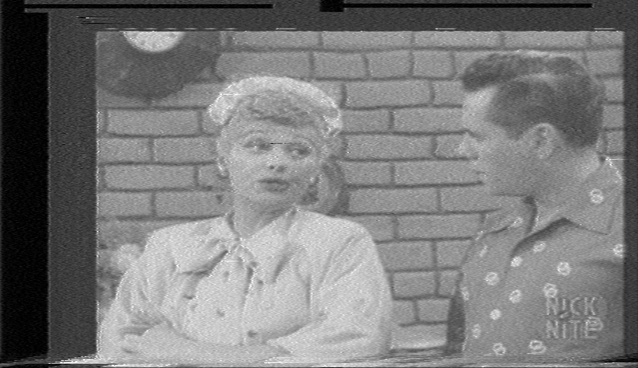
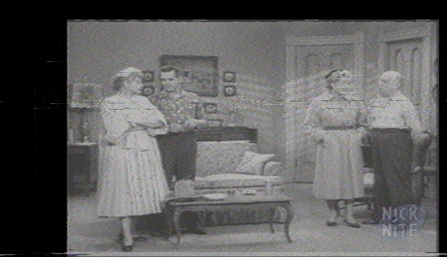
Lucy monochrome test:
http://www.mediafire.com/file/oaeqsfs6xguy9at/MonoChromeTest.r8/file
The only color is the blue Nick at Nite logo. This sample has minor tracking errors showing up as static near the top of certain frames. This was decoded with my tweaked filter settings as explained earlier to recover more bandwidth. Also, I had some of this on my test tape, but that one has terrible tracking issues (crappy tape). So this sample is from another tape that tracks better. It's also worthy of note that these tapes are about 20 years old and they were recorded using a different TV/VCR combo than my machine. The source was MPEG-2 satellite TV.
I don't think I noticed this before, but I'm also getting some constant noise in the upper side of the band above the FM video carrier.
Source decode:
Color decode:
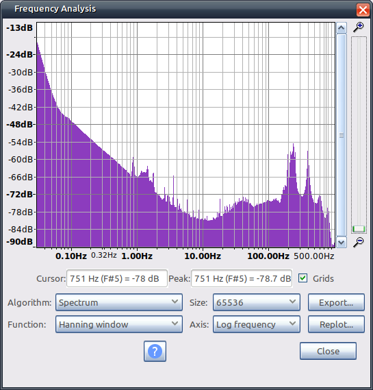
Spectrum:
Last edited by Titan_91; 10th Oct 2020 at 15:29.
-
Yes, I got lost by information overload.Originally Posted by Titan_91
I think the formula applies for luminance, but I used it with a wrong assumption about the baseband bandwidth
You're right about the multiple carriers, but each one can be treated as a separate channel.
So, if the luma has a limit of 3 Mhz, then the Carson outputs:Originally Posted by oln
2* (3MHz + 1MHz) = 8 MHz
Plus the 3.9 MHz modulation shift 13.9MHz 12.9 Mhz !! (That's why I didn't approve my finals)
Here it is!Originally Posted by Titan_91
So, they capture the output of the low-pass, not the delta-sigma pulse train.
This loses an important information for de-jittering and relies on the machine servo loops.
Further hardware can be implemented to deal with this, a frontend that de-jitters the sigma-delta carrier prior to sending it to the 13.2 MHz lowpass
I know about electronics, not a lot, I will try.Originally Posted by oln
The academic way involves a lot of maths to do this, I will load the circuit on NI Multisim, and simulate it to see what it produces, thanks for the highlight of the part of the schematic of interest.
Here is what I see:
I highlighted the parts of the schematic that can change the frequency response.
The yellow highlighted parts are always active.
The green part is enabled in SP mode.
The cyan part is enabled in LP mode.
The magic is produced on the emitter of Q3004.
When in LP, the network of the right gets enabled and paralleled to R3027 while the network of the left is disconnected by QR3002 and "floats".
In SP mode, the opposite applies.
QR3007 and QR3002 are mutual exclusive
The right network marked with cyan gets only connected by the 10k R3029 resistor and the base resistors of QR3002.
As its impedance seems to be an order of magnitude higher than the green network it is safe to assume it doesn't interfere in SP (but I will check this, I'm not sure)
Here some measurements I made on the new capture to compare it with the older ones and make conclusions:
Your modification of the lowpass frontend seems to be working.
There is more amplitude on the higher frequencies, specially over 10MHz.
However that peak around 7 MHz makes me doubt about it.
I don't know if that is present on the signal or it is an artifact.
I guess it is an artifact because is strong as the FM carrier and wide.
Note that in the waterfall plot there is practically no colour on the downconverted chroma, around 625kHz
And here the NTSC colorbars as control:
I use Linux as my main operating system since 1999, and I'm proud of my choice.
But as a downside, it can get it configurations rotted easily between updates. It improved a lot on this aspect from where it was.
An useful command I use to debug PCI devices is:
lspci -v
If the device shows in the list, then its about getting the drivers to load.
I'm glad you found what was failing!Last edited by VideoMem; 10th Oct 2020 at 19:11.
-
Audiovisual Manipulator

- Dec 2019
-
Ok, so I did multiburst test with my setup and here are PAL VHS samples in SP and LP mode: https://mega.nz/folder/XBADTKbb#GLFpHAA7lHkPtFKAG20vkw
Simultaneous capture with CXADC and Panasonic DVD recorder was made so you can preview video stream the standard way.
The last piece taking about 12GB of space is full CXADC capture which will finish uploading soon in 8GB 7z archive.
[Attachment 55412 - Click to enlarge]
Edit: I forgot to mention the tape is S-VHS type recorded in VHS machine (Panasonic NV-HD630).
Chroma part has some weird flickering I don't know how to eliminate.
I attach samples to the post in case something happens with link in the future: -
Interesting. Do you think this due to multiple sync signals being present in the base band? 15,750Hz for horizontal and 59.94Hz for vertical? These are square waves though, and the Wikipedia article states the formula doesn't apply very well to square waves. I'm still trying to wrap my head around it.Originally Posted by VideoMem
I apologize if it sounds like I'm nitpicking on the Carson subject, but I read oln's post like that is the upper limit of a base band signal before it is modulated to 3.4MHz to 4.4MHz NTSC. Doesn't the Carson formula only apply to the signal after it has been FM modulated? If so, then 2* (4.4MHz + 1MHz max deviation) = 10.8MHz. We can capture a Nyquist frequency of up to 14.3MHz at 28.6MSPS, and 17.9MHz at 35.8MSPS. I could be totally wrong on this, as again I don't fully understand the math involved (or if the Carson formula even applies to VHS luma).Originally Posted by VideoMem
Edit: I'm wrong on the Carson formula. I misinterpreted "highest frequency in the modulating signal." So yeah, 2* (3MHz + 1MHz) = 8 MHz. The highest frequency in the modulating signal is 3MHz because the CVBS input is band limited prior to FM modulation.
I didn't make any frontend changes on the hardware side. When I referred to my tweaked filter, I mean the cutoff frequencies in vhs-decode. The source signal path and equipment is unchanged from my other tests.Originally Posted by VideoMem
That's the bar of noise I'm seeing at the top end of the spectrum then. I didn't think it was there before, and you proved it compared to my color bars test. Good find! I have no idea what that is. I doubt it's an image of the luma signal, as images tend to be lower in amplitude. It might be some noise on the tape? I am using a different tape for this monochrome sample, after all.Originally Posted by VideoMem
The chroma signal is barely present on the monochrome sample. I think I read that chroma is AM modulated on VHS. If so, that explains the lower amplitude vs. the color bars.Originally Posted by VideoMem
Thanks for the advice. I recently switched to Linux about a year ago. I built a new Linux Mint based gaming PC and my older PCI equipped capture machine is the the one I was using prior to that.Originally Posted by VideoMem
Last edited by Titan_91; 10th Oct 2020 at 21:41.
-
Great!
I've finished the simulations of the luma filter circuit:
Here are the results:
500 mVp input, dB units
(LP Mode frequency and phase response)
(SP Mode)
(The circuit reconstruction)
(The files, it includes the schematic and .csv files with the detailed graph responses)
RF luma active filter.zip
Guess what.
There is a notch around 8Mhz!!
The lower notch around 625kHz is expected, it blocks the downconverted chroma carrier, but the one at 8MHz is a mystery.
Both Q-peak potentiometers were set to 50%
I will answer the recent posts in detail later.
Thanks for the feedback!!
Edit: ignore the file names, the correct name is "Luma active filter", there is no amplification on this stageLast edited by VideoMem; 11th Oct 2020 at 01:02.
-
I've been studying the schematics for the NV-HD100
After the above luma filter, the signal goes into a module VEFH29D (near Unobtainium)
It is a ceramic? board with an AN3552FBS chip and a MSM7403MS CCD delay for "copying the last line on dropout" and a couple of supporting external components (includes electrolytics, If you have one of these check them)
I can't find any datasheet for these chips nor the module, but the service manual shows the inside block diagram.
So, I tracked the RF luma path (on playback mode) down the river to Video Out (CVBS/Composite)
Here is what I got so far:
I guess the green part network after de FM demodulator (pin 43) is the de-emphasis circuit ( I need to verify that with simulation ).
I marked with green all the parts of the circuit that can change the frequency response.Last edited by VideoMem; 11th Oct 2020 at 13:34.
-
Capturing Memories
- Jan 2016
- Member Since 2005, Re-joined in 2016
-
There is a technical guide for JVC about video processing of the signal in their VCR's, I though I would share it here that might lights up a bulb in someone's head:
http://www2.eng.cam.ac.uk/~dmh/dmh/JVC-HR-S9500-Trn.pdf -
I'm getting concerned about what of the two RFs we are capturing from.
Are we capturing the RF-Y or the RF-C?
Because the head amplifier has an AGC at RF-Y, whereas the RF-C is only a buffer of the raw signal.
If we're capturing from RF-Y the chroma part which is QAM will get distorted by the AGC, and if we're capturing RF-C we depend on the amplifier bandwidth to demodulate Y.
The RF-C amplifier might have not enough bandwidth to deal with the FM luma, and the AGC at the luma distorts the chroma.
Both signals comes to different pathways right after the amplifier:
Take a look at this:

I finally undestood why the devices have four heads.
Two heads are used in SP, and the other two in LP.
They are not interchangeable as them are designed with different frequency response.
I guess we're on the RF-Y pathway right after the AGC, that explains why we get scrambled chroma.
I'm thinking how to solve it the easiest and cheapest way.Last edited by VideoMem; 11th Oct 2020 at 16:51.
-
Audiovisual Manipulator
- Dec 2019
-
In my video machine there is single output labeled as RF-YC and has common chroma amplifier and no AGC block so I'm kinda lucky (but signal strength does not matter that much with FM signals):
[Attachment 55458 - Click to enlarge]
This is head switch I probed on playback in other machine (LG DVC-5930):
[Attachment 55457 - Click to enlarge] -
I thought you had a Panasonic FS-200.Originally Posted by Zcooger
Of what device we're talking about? We re talking about the NV-HD630, right?
Yes, you're lucky to have an AN3369SB head amp (there is no datasheet on the net, but it have the same pinout as the AN3360SB)
FM signal strength doesn't matters too much at RF-Y for Y decoding (FM), but it matters at RF-C for C decoding (QAM)
However fluctuations in amplitude at FM causes changes in the S/N ratio, that's why RF-Y has an AGC later in the signal path, or integrated in the same head amplifier IC
The following applies to other VCRs:
According to the service manual the head amplifier of the Panasonic NV-FS200 is the same as in the NV-HD100
Both machines uses the AN3336SB (Panasonic NV-FS200 & NV-HD100)
For the LG/Goldstar VTRs, I can't find the service manual for your model, but other LG VTRs uses the LA71750EM from Sanyo
They integrated the head amplifier, filters and demodulator / colour module in a single chip.
Pin 21 on that chip is our wanted RF Y/C (LG/Goldstar/Sanyo)
In summary:
- If you have a machine with an AN3360SB/AN3369SB head amplifier (NV-HD630), you must capture the signal from the pin 30 of that IC.
- If your device have an AN3337NSB head amp (NV-FS200 / NV-HD100), you must capture the pin 26 from that IC (not the AGC RF-Y path)
- If you have an LG/Goldstar/Sanyo? machine with an integrated head/amp demodulator LA71750EM, your capture tap is at pin 21 of that IC
I guess both AN336xSB and AN333xNSB are the same amplifier design, but the later have the AGC for FM-Y integrated in the same die.
The chroma output at pin 26 is compatible with the signal of the 336xSB at pin 30.
A ceramic/polyester 0.1µF 1µF bypass/DC blocker is recommended to extract the signal from the circuit.
If a current buffer is needed, it can be done with an RF transistor in emitter follower configuration such as the MSC2295, or any RF transistor with a collector gain bandwidth product of at least 150 MHz.
Something like this:
0.07% THD @ 4MHz 1Vpp, according to the SPICE simulation, flat response up to 100MHz
Some notes on the components and PCB design:
All resistors are metal film type with the exception of the 1MOhm bias one. It can be plain carbon.
The 10nF capacitor could be ceramic and needs to be placed as near as possible to the 10K emitter resistor ground and the collector of the transistor.
All traces should be as short as possible. There is recommended to have a ground plane surrounding the board, or in the back (2 layer design)
The 100ohms resistor is for safety to the IC in the case the transistor shorts and the input capacitor shorts.
The 47µF electrolytic is not critical, but it is recommended to have a rated voltage near to the supply voltage (not lower than that, and not much higher).
The circuit should be near to the head amplifier as possible.
I do not include possible effects of the signal reflection between the output of the device and the ADC card (this lack of proper impedance match to the transmission line), it could be improved to a line driver with impedance matching for driving a coax and proper terminating resistors.
PD: I like the music you choosed for the multiburst test. It is so "technical difficulties, please stand by ....", I can hear it all dayLast edited by VideoMem; 12th Oct 2020 at 20:43.
 Quote
QuoteSimilar Threads
-
what is current "best" file uploading/sharing service?
By hydra3333 in forum Newbie / General discussionsReplies: 15Last Post: 30th Aug 2015, 03:39 -
How i can encode audio of "REMUX" to "BluRay.720p.DTS" wit handbrake?
By VideoHelp4Ever in forum Blu-ray RippingReplies: 1Last Post: 2nd Jul 2015, 11:41 -
[SOLVED] "--ipratio" "--pbratio"+"--scenecut" "--minkeyint" / "--keyint
By Kdmeizk in forum Video ConversionReplies: 14Last Post: 21st Jun 2015, 07:21 -
[Help] Problems with the "Title Button" in the "VTS ROOT" and "VTS Normal"
By kirous in forum Authoring (DVD)Replies: 8Last Post: 1st Nov 2014, 12:31 -
How to convert "Still Image" to "AVC file" (like as Godzilla Blu ray Menu)
By ningnong132 in forum Video ConversionReplies: 2Last Post: 8th Sep 2014, 04:23