


Hi All.
I have started building a new pc, however, would like to make sure that I am doing the correct things before I proceed any further.
The guide accompanying the graphics card (GTX 260) instructs to connect two INDIVIDUAL PCI Express (6-pin) power cables directly from the power supply to each individual connector on the graphics card. The power supply has two 6-pin connectors but they are on the same single cable. Does this qualify as being two 'INDIVIDUAL' cables or do I need to use the two molex to 6-pin adapter cables that came with the card to ensure two separate cables are used?
Here is the manual for the motherboard - http://europe.giga-byte.com/FileList/Manual/mb_manual_ga-ma785gt-ud3h_e.pdf
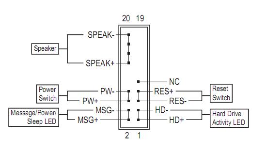
On page 28, it states regarding the F_PANEL (Front Panel Header) - 'Connect the power switch, reset switch, speaker and system status indicator on the chassis front panel to this header according to the pin assignments below. Note the positive and negative pins before connecting the cables.'
How do I figure out which pins are positive and negative. There is no written indication of this on the PSU connectors. The wires are red and white, orange and white, green and white and blue and white. Am I correct in assuming that the white wires are all either positive or negative? If so, which?
The PSU does not have a connecter with 'speaker' or an abbreviation of speaker on it. The only other connectors are HD AUDIO, 1394, USB, AC'97, SHIELD, TPA+, TPA-, TPB+, TPB-, VG AND VP. How do I tell which way around these are to be connected, ie. which side is positive/negative?
Is the following correct (the diagram is on page 7 of the manual)?
I have plugged the connector of the fan that came with the case (at the front of the case) to the socket marked 'PWR_FAN', and the connector of the fan that came with the case (at the back of the case) to the socket marked 'SYS_FAN2'. There is nothing plugged into the SYS_FAN1 socket or the 3-pin PWR_LED socket.
There are two single connectors marked +P LED and -P LED. Are these to be connected to the MSG pins and not to two of the three pins on the PWR_LED socket?
Thanks for any help.
PS Sorry for calling them 'sockets'. I find it easier to explain that way.
+ Reply to Thread
Results 1 to 9 of 9
-
-
The (2) pci-express connectors on 1 cable are fineOriginally Posted by A Traveller
None of those F-panel connectors is polarity sensitive
black is usually ground, and positive is usually red
speaker (if your case has 1 built in) connects from the case to the mobo pin headers, not the psu
connect the +p and -p led connectors to the outer of the 3 pwr led pins
ocgw
peacei7 2700K @ 4.4Ghz 16GB DDR3 1600 Samsung Pro 840 128GB Seagate 2TB HDD EVGA GTX 650
https://forum.videohelp.com/topic368691.html -
Some cases have a three wire PWR LED that also functions as a sleep indicator, usually with a two color LED. Sometimes the case pins don't match the MB socket and you may have to move them on the connector. Or it may just have a regular two wire PWR LED that only shows that the PC is on and flashes during sleep. If you hook any of the LEDs backwards, they just won't light and you can reverse the connectors and try again. Since you have a lot of white wires, those would be the negative leads.
The PWR switch and the RESET switch aren't polarity sensitive. The SPKR isn't usually either, but may work better connected correctly. Some newer MBs use a solid state speaker, so it may not operate if connected backwards. The good news is you can't hurt anything if you hook any of the front panel connectors up backwards. They are logic level and protected from that.
Be very careful of the front panel USB and 1394A connectors. Both carry 5VDC and if you hook those wires to ground your power supply will shut down almost instantly. Usually with no damage, but I wouldn't want to test that. Most PC cases have a polarized plug with all the wires in it for the 1394A and the USB front connections. If you have the individual connectors, spend some time learning where they go. Most all I have seen are clearly marked on the sides of the connectors. If in doubt, don't use those connectors at all.
Front panel connections:
-
Thanks for all the help. I really appreciate it!
I have followed all your instructions but there is something else. There is also a socket with 8 holes on the motherboard. Next to it says 'ATX 12V 2x4'. Does anything need to be connected to this?
Another thing I've noticed is that the housing of graphics card is covered with plastic protective film like how they have on new cell phone screens, etc. Is it better to peel this off for cooling purposes or should it be left on?
I have read and read and read before starting building the pc, however, it seems to be the straightforward things that haven't been covered well anywhere!
Thanks. -
That 8-pin is your cpu power connector, the pc will not start w/o that connectedOriginally Posted by A Traveller
Yeah, peel that chit off lol
ocgw
peacei7 2700K @ 4.4Ghz 16GB DDR3 1600 Samsung Pro 840 128GB Seagate 2TB HDD EVGA GTX 650
https://forum.videohelp.com/topic368691.html -
"That 8-pin is your cpu power connector, the pc will not start w/o that connected"
HAHA, well I did manage all the other difficult stuff!!!! HAHA.
Thanks. -
Here's a slightly old guide that may help with the basics. It's in PDF format and I think it's still available on RapidShare. If not PM me and I can repost it there. https://forum.videohelp.com/topic315746.html#1619108
-
Hi redwudz.
Thanks for the link. I've now completed the build and I don't know when I'll be building another computer again!
I had read almost every page of every manual that came with the hardware, including the motherboard manual, as well as the following website.
http://www.pcbuyerbeware.co.uk/Build.htm
It was so frustrating having to read all of that and not being able to start the fun stuff straight away!
Regarding my previous question, I tried the P LED in the first and third pins of the PWR_LED, the first and second pins and also in the MSG pins but none of them worked. I only get the hard drive activity light, but no power light. This is not a big deal as I now have a bigger problem which I'll probably post in the relevant section (problems with dual monitor!). -
Use the two MSG connectors on the front panel socket that I posted earlier. You can also test the case PWR LED by switching the HDD LED leads in place of it. If it works, then maybe your case PWR LED is defective.Originally Posted by A Traveller
 Quote
QuoteSimilar Threads
-
Building an HTPC
By joepic in forum Media Center PC / MediaCentersReplies: 6Last Post: 16th Feb 2016, 16:46 -
Building a new PC - This is annoying
By Des in forum ComputerReplies: 5Last Post: 9th Jul 2010, 16:54 -
building a new computer
By gooberguy in forum ComputerReplies: 123Last Post: 3rd Jul 2009, 17:21 -
Building a PC!
By Nitro89 in forum ComputerReplies: 16Last Post: 4th Nov 2007, 14:42 -
Questions about Building my first PC
By navi310 in forum ComputerReplies: 18Last Post: 28th Aug 2007, 19:07