


So, are there any more ideas what to check next ?
Try StreamFab Downloader and download from Netflix, Amazon, Youtube! Or Try DVDFab and copy Blu-rays! or rip iTunes movies!
+ Reply to Thread
Results 151 to 180 of 556
Thread
-
-
I am concerned that we do not understand what happened to 0.17 volts from D1.8V to the the DMN-8652 or was that +1.86V measured at the JCP8059? That is a lot of voltage lost. It would take an ampere of current and .17 ohm of resistance in the pc board to cause that. Can you measure the resistance from D1.8V to the point where you measured the +1.86V? If we know that we can determine the current and if the current value is reasonable.
There is also a second source of +1.8V from IC5307. It is labelled DC1.8V but the schematic shows it goes to the RAM drive. Can you confirm that is correct or is it possible there is an error in the schematic and it is reversed that DC1.8V is going to the DMN-8652 and not D1.8V?
PS There is a part LC1401 on the media processor schematic. Is it possible the voltage is lost in this part? The power used by the DMN-8652 is <2.7 watts. How hot is it getting? -
hehe looks like we think the same way ) I also wondered how it can happens. I measured once again voltage on Cn5302 (sheet 1) pins 1,2 & 3 - there is 2.02V and on Cn 1002 (sheet 5) pins 21-24 - there is 1.86v already. After I measured 1.86 on check point near DMN - I also start looking where 2.0 becomes 1.86v and found that 1.86 already comes to digiboard. So the reason is on main board somewhere under the drive. It will requre to dismount drive to get access there.
DMN becomes quiet hot - upto +65C I measure during work. I tryed to place it closer to the bumped shield (there is a piece of material between chip itslef and upper cover - like a wet rubber, but there is also a small space between it and metalic body - I tryed to pack it closer to make a good thermo contact, but there was limitters on boarder of can so I can`t make it more closer then it is.
Its hard to find parts on digiboard because they placed very compact most of them have no space for names. I didn`t find LC1401 on board , but I measure voltage on checkpoint near DMN Vdcc pin and Cn1002 pin 21-24 and there is exectly same voltage 1.86V.
IC5307 is absent in my unit because it only for models outside Europe. -
That was good work. The LC1401 is between CN1002 and the DMN-8652 so it cannot be the cause of the drop.
That wet rubber sounds like a thermally conductive pad. It is normally used between a device and a heatsink in place of paste, thermal compound but it must make good contact with both. It sounds like a thicker piece is needed. The material normally does not shrink.
Here are two links to companies that make this material.
http://www.trocad.com/data_sheet/T-177-T228.php3
http://www.micchem.com/products/Silicone.htm
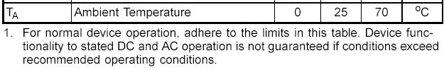
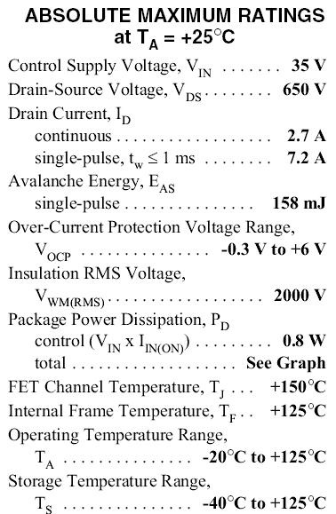
This is the temperature information for this type of IC from LSI,
-
Some news of more tests from the land of DR-MV1S loading & repair. Once again, this is a different unit, but very relevant to this thread as the circuitry is the same.
I have been running the unit without the top metal cover, and with the DVD drive sitting to the side of the main unit's footprint (extended the power cable with a PC HDD extender cable).
The main aim was to measure heatsink temperatures but I also had the "loading" thing occur too, see below. My unit is still modified as per my previous post in this thread.
Heatsink temps first: STRG6653 heatsink, DR-MV1S idle with disc in drive 49.5 degrees C. Rises by 1 degree (temporarily) when a disc is inserted. Then when dubbing from VHS to DVD, 15 mins elapsed, 51.4 degrees C.
Metal can of digital board, 42 degrees C at idle. No figure yet when dubbing (fingers say over 40 degrees but not hazardously hot).
Now, the "loading" experience. Saw this twice in one evening: first time, unit was fully closed up and had been at idle for some hours. I decided to try dubbing again. After unit had been dubbing for 15 mins, while I wasn't there, unit shut down. Might or might not have showed "loading". Second time, using the same DVD-RW, unit was running without lid, so cooler I guess, and this time I heard clunks from the DVD drive, then saw "loading" on the display. Inspection of the DVD surface showed it stopped at same place on the disc as before.
Changing the DVD disc to one I had previously written the entire disc & erased (ie. a good one), I completed a 3 hour dub successfully.
So, this time I am sure the "loading" is due to a bad area on the media, but have yet to confirm by using it in the PC. Certainly it shouldn't be thermal when the unit is open.
Those temperatures would be even higher with the top cover back on, so my next step is to fix more heatsinking to the STRG6653 and perhaps drill some holes in the top cover. Also trim the DVD drive support bracket so it doesn't trap hot air around the digital can. -
It would be interesting to know the air temperature rise from ambient inside when the unit is closed up. With the unit open, the ambient temperature is room temperature but the internal air temperature closed up is the actual ambient to which most parts are exposed. The highest ambient temperature to which any IC is exposed will probably be the inside the can due to a heated enclosure within another heated enclosure.
-
Yes it would. I suspect they're going to be quite worrying! OK, before I modify further I'll run the DR-MV1S with the top cover back on and my indoor/outdoor digital thermometer in. It will report ambient at the same time which is nice

-
Ad far as I noticed "Loading" means reseting CPU and initializing routins start. It may happen by different reasons - such as faulty electronics that cause in some situations such problems - like in PC faulty RAM, power supply problems etc.
Or , as you said, programm problems - if its is realy problem caused by bad disc (media), then it more looks like programm error. I guess it can be fixed only by updating firmware. -
Hi - I've a PAL DR-M10, when I bought it I was aware of the "loading" problem, but I was persuaded by Lordsmurf's comments about this machineOriginally Posted by MiG-45

It's a great machine and I'm 100% satisfied by the quality of recording and dubbing; regarding the "loading" problem I've experienced it only once, but now I'm pretty sure that it was caused by poor DVD-RW media. Since then I've been using only Panasonic DVD-RAMs and I've done many hours of recordings without any trouble (power save=ON). -
Yes, I had read lordsmurf's comments early on about bad media causing "loading" too. Perhaps a bad media causes a "panic" in the firmware and it ultimately results in a restart....perhaps the action of a watchdog timer not being 'kicked' in time? And as Mig-45 says, other things are well known to cause restarts in microprocessor systems : RAM timing errors, chips operating outside their temperature specs, power problems (on internal voltage rails....) the list goes on.
I think it's clear though, that once bad media are eliminated, a stock unit of M10 or MV1S would still have a problem with the top cover on, due to the heat buildup.
I am pleased with the results I just got, as previously I had not managed to complete a dub without the unit being "from cold", ie. turn it on at the wall and start recording immediately. That tallies with others comments about not leaving it on 24/7 if you want reliability.
However, I'm keen to find a solution so I can rely on the unit any time of day or night, stone-cold or warm.
There's more to do yet, but some progress is being made I think. If I can increase reliability by good heat management, and then if I have to use top spec media to avoid "loading", I'm happy with that. -
Well, I agree - its best buy for this price! The only thing I really miss - I understand it after using DR-M10 for few months is HD! I have 3 DVD-RW disk I use them to transfer records to my computer. So I`m looking forward when DR-MH55 will appear in Europe! You can find out more on JVC`s Japanise site - victor.co.jp. You don`t need to know Japanise to read its specifications.
p.s. sorry for lil bit offtopic ) -
OK, the scores on the doors. Top cover on, and don't forget my fan is running at full speed (39R resistor shorted out, 12.1V is now applied to fan).
After 1 hour spent with unit at idle, shiny (digital) can is measured at 39 degrees C. After 30 minutes dubbing (VCR deck in play and DVD recording) 41 degrees C.
Now for the STRG6653 heatsink. No temp at idle as the sensor was elsewhere, but after 30 minutes dubbing we have 49.5 degrees C.
(Not that dissimilar from measurements with the top cover off.....)
After 1.5 hours dubbing the unit shuts down (wasn't there so can't state if "loading" occurred or not) but - get this - upon return to the unit, the fan is off (usual state for a shut-down unit of course) and STRG6653 heatsink is over 70 degrees C (my thermometer stops at 70). The usual warm-spot on top of the unit is there, above the 6653 heatsink. You can now see why! (I have no measurement for the digital can now as the sensor was moved).
Starting up the unit operates the fan, and the 6653 heatsink temp quickly comes down to 49 degrees C.
(The unit was measured in a room with 23 degrees ambient.)
What do you think trhouse? -
Sorry for the delay. I have been without an Internet connection for most of today. The fact that the can and heatsink did not change temperature much with the cover on is good news. It means the internal ambient temperature cannot be much different than the room ambient of 23 degrees C.
Here are the specifications for the STR-G6653.
It should be ok even with the heatsink at 70 degrees plus. The 70 degrees occurs when the unit is not operating which helps.
Is the metal can design for the M1V the same as the M10 with the dimple and the thermal pad inside to make the can into a heatsink? If that is working then the temperature of the DMN8652 should be not too much higher than the 40 degrees C measured for the can. If the thermal pad is too thin like mig-45 found in his M10, that could be a problem because the DMN8652 temperature can be much higher for a lack of a good thermal path to the can. -
I still looking for local silicon thermal pad resellers. Only I found in nearest shop is exacly the same thin as native M10 ( Don`t wanna make hamburger and using two thermal pads. Maybe will try to use more thermal compaund to fill space between dimple and thermal pad (or thermal pad and DMN itself).
Also must notice that temperature condition inside M10 is quiet good! There are holes on its sides and small holes on botom part of case - so the only way to make it even better is to put a small fan under the digital board (there is some space there) and the holes are near! But it doesnt` change situation too much - max 5C less ! -
I would not use two thermal pads sandwiched together either. Too much chance of air pockets between layers unless enough pressure can be applied to eliminate them. Air is a very poor thermal conductor. If you can achieve a very good thermal path from IC to can, the can temperature will be close to the IC temperature.
I have been looking at the material list for the M10 some more. Nearly every resistor in the M10 is a 5% value. I wonder if JVC might have slipped up and used 5% values in those voltage determining circuits instead of the precision 0.5% parts in some units. The greater variation in voltage could be the cause of the more traditional "loading" problem which others have mentioned is solved by resistor changes. -
A little more on high internal temperatures: I checked out "unit off" mode with/without power-save on, since I noted the STRG6653 heatsink was at or over 70oC in off mode, after a 1.5 hour dubbing-shutdown. The top cover was off this time to see what the effect of improved ventilation was.
In "unit off" mode with power save on, and the top cover off, STRG6653 heatsink at 61oC. Same conditions with power save off, 63oC.
The STRG6653 is happy at up to 125oC as you say trhouse. Looking at the pcb though, it is already browned so perhaps that is not so happy! It's a resin bonded paper type, not as good as fibreglass (the green ones).
Early on, I upgraded some resistors from SM 1/16W to wire ended 1/4W, to eliminate problems with dissipation.
I always thought the fan was running during "unit off" when power save was 'off'. Could someone else confirm this please? It did so once but then not again. I may have blown a transistor as trhouse said, I will check schematics but that will be tonight.
It is good that there are extra holes in the M10 top cover to provide ventilation, I will be adding holes in the top cover (and a fan cutout or louvres if I can get a metalworker to help). Maybe also set the fan circuit so that it runs fast in operation and gently in "unit off" mode to lower the temp of the 6653 heatsink.
The dimpled digital can in M10 sounds like what I have in the MV1S also, I will post a picture for comparison. I haven't yet opened the can to see if the thermal pad contacts both can & chip. Pressing on the dimple doesn't cause much flexing, if it flexed a lot I would say there was no contact. -
The picture I promised, plus one of my mods to improve airflow beneath the DVD drive.....
DVD drive support bracket, after modifications.
http://www.geocities.com/simonwalls/Img_4840.jpg
Digital board cover.
http://www.geocities.com/simonwalls/Img_4838.jpg
Hope you get your connection back soon trhouse. -
I was in a store tonight and found a M1V plugged in on their shelf. It was flashing the "loading" message and two blue lights at either end. It was manufactured April, 2004 Beijing, China.
All the buttons did not lock out. On the left side is a button labelled, "dvd/vcr" and two green LED's, one to the right of the button and the other on the dvd ( right ) side which alternate and seem functional.
I also noticed that the M1V has no vent holes on the side, top, or back ( except for the fan ). It does have vent holes on the bottom.
My connection seems back to normal. -
The analysis of the service manual has not really turned up anything that should cause failure at room temperature even though it is obvious some parts are operating very hot. Mig-45 finding that the thermal pad is not making sufficient contact to the DMN8652 and the metal can is certainly of concern but that is a mechanical fit issue.
I went back to all the threads regarding this issue to see if anyone ever mentioned what was replaced in a unit that had been returned to the factory. Someone with the handle CEF did. CEF noted that when his unit was returned from factory service ( in Hawaii ) the invoice was for $0 and indicated the following items were replaced,

These are JVC's part number for a leaded, 1/2 watt, 1,000 ohm, 5% tolerance, carbon resistor. No such part is listed in the M10 manual so I am assuming that this is the replacement part for something else. Combing through the parts list yields the following,
Regulator board: six leaded resistors of values 68, 8.2, 680, 820, 10K, and 100 ohms.
Digital board: none
Main board: six leaded resistors of values 10K ( qty 2 ), 10, 15K, 100, and 330 ohms.
Operation board: one leaded resistor of value 330 ohm.
Switch display board: four leaded resistors of values 10K, 3.9K, 27, and 1.8K ohms.
The above are all 1/4 or 1/2 watt resistors. The closest two values to 1,000 ohm are R5327 ( 681 ohm ) and R5328 ( 820 ohm ) on the regulator board both 1/4 watt parts. These parts under normal operation dissipate 82 mW and 99 mW, respectively. Since these are 250 mW parts they should have no problem unless they are defective. These resistors are in series with each other. They are used to drop the -29 volts down to -12 volts with the aid of a zener diode. Here is a picture of them,
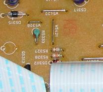
R5333 to the left and above these parts is a 1/2 watt resistor for size comparison. If the parts are defective, JVC could replace them with good 1/4 watt parts so it may be hard to tell if they were changed but if they used 1/2 watt parts, JVC would probably have to mount them like R5333 for space reasons. -
Funny that the one in the store was flashing "loading" !
I have a local metalwork company making arrays of punched holes in my top cover.
They are to be located on the top surface, above STRG6653 to improve "unit off" temperatures, and on the side beside STRG6653 for the same reason. This is a precautionary measure really. (Perhaps I will fix the temp probe to the TO220 package itself if feeling brave!)
Also holes on the right hand side at the front to permit cold air to flow beside/above the digital can then exit thru the fan. With my cut-down DVD drive support bracket I should get airflow over the digital can. After that, I may open the digital can to check out the thermal pad contact.
I will re-test temperatures with the top cover on when I get this back, it will be after the weekend.
Thanks for poring over the service manual, its appreciated. Do you own an MV10 or are just interested (technical challenge?). If the latter, you have all our thanks. -
Those extra holes at the top should aid convection cooling in standby. More holes means increased air flow with the fan but it is air flow past the hot components which matters most. The holes are going in the right places for that. Looks like the "loading" issue has not recurred in your unit.
I do not own one of these units. My interest was raised when mig-45 was discussing with lordsmurf about doing his own repair and that he had gone as far as to buy the service manual. When JVC declined to help him and being familiar with switching power supplies, I decided to see what could be done.
If we could have discovered what the factory does to solve the "loading" problem in the process; I thought it would remove the mystery and alleviate doubts about what seems like a fine piece of equipment. It would take someone who has had the repair done by the factory like "CEF" to confirm where those two 1/2 watt resistors were added. There are only three 1/2 watt resistors in an M10 and their values are 10, 100, and 330 ohm so two new ones would be pretty apparent.
Glad you joined the thread. Three heads are better than two. -
How about going back to the main topic ... The JVC DR-M10S and the "LOADING" problem. For those of you who have had this service done by the JVC Factory Service Center please share your experience ... how quick was the turn around? how does it work now? any other info. This would be much appreciated as I'm about to send mine in.
Also, it should be noted that the service rep I spoke to said they will only do this service on recorders under warranty. -
tamgelikah,
Would you be willing to take a picture of the regulator board, particularly R5327 and R5328 before you send your unit in? I suspect that these are the parts JVC is replacing to solve the "loading" problem but there is no way to confirm it unless someone can note what parts were in their unit before JVC makes the changes. These parts are inexpensive and anyone who can solder can replace them in a few minutes.
"CEF" who reported the change to two 1/2 watt resistors mentioned that JVC's invoice indicated $100/hr for out of warrany repair. -
I posted this in another thread, but it also applies here.
I got the loading error 100 days into the 90 day warranty.
Called JVC service, and they said they would repair it free of charge.
From the time I dropped it off at the post office, I had it back within 5 days. I have since been made over 600 DVDs with it in the last 9 months, with NO loading errors whatsoever.
Runs like a top now, and the picture quality is great!
Dan Ginnetty -
I bought my DR-M10 in April 2005 and I got the "loading" only once, but I'm pretty sure it was caused by a poor quality DVD-RW disc.Originally Posted by trhouse
I'd like to take a picture of the parts under suspiction (maybe they've been replaced with different parts from a given point of the production run), but is it possible to open the unit without compromising the warranty? -
From the JVC website:
"Q: My DVD recorder has experienced green or white noise in the picture display followed by the word “Loading” flashing continuously on the unit’s FDP. Unplugging the unit clears the "Loading" indication and restores normal operation. How can I prevent these symptoms from re-occurring?
Models: DR-MV1S, DR-M10S, DR-MH30S, DRMX1S, SR-MV30U
A: A limited number of units of certain models of DVD recorders (Models-DR-MV1S, DR-M10S, DR-MH30S, DRMX1S, SR-MV30U) have experienced the symptoms described. While manually resetting the unit, as set forth in the question, restores normal operation, the symptoms may reappear. JVC has identified the cause of these symptoms and will make the necessary adjustments to affected units to eliminate the likelihood that the symptoms reappear. Adjustments will be made free of charge at JVC Factory Service Centers. Click the Factory Service Center link at top left of this page to obtain your nearest location. Please call 1-800-252-5722 and select option 4-3 if you have any questions regarding this process."
Link to find the nearest JVC Factory Service Center:
http://www.jvc.com/ascsearch/mqlocator.exe?link=index
It has been reported widely that out of warranty units are also being repaired free of charge, and for the vast majority of people who have the service done the problem does not re-occur. -
I have now got a top cover with lots of ventilation holes in useful places, but it has not been refitted as I started exploring the digital board further. I found out that the junction pcb to digital pcb connector could be detached with a little more force than I was willing to use the first time around, thus I did not see this before.
Below are links to some photos of the digital board 'underside' which normally faces downwards.
I noticed that there are 2 1/4watt resistors (although they may be indeed 1/2 watt in these modern times) mounted on their leads. This looks like a factory mod -- perhaps the one you are seeking trhouse? I also now have been told that (if it can be believed) that this unit has been modified to 'fix' the loading problem. My experience is that it still does it when dubbing.
The resistors are both 1.0k by my meter. Later I will try to work out where they are attached on the schematic, but for now I only have the pictures.
If anyone knows how to reveal the software version (apparently modified units were reflashed) then we can all check and report.
http://www.geocities.com/simonwalls/Img_4922.jpg
http://www.geocities.com/simonwalls/Img_4924.jpg
http://www.geocities.com/simonwalls/Img_4925.jpg -
oyster,
I would love to know if your M10 now has R5327 and R5328 on the regulator board changed to 1,000 ohms either with 1/4 or 1/2 watt parts. Yours being a late model should have the "loading" fix in it already, but I would not go so far as to have you void your warranty. The warranty is 90 days I believe.
emlsnws,
Yes, that is very close to the answer I was seeking. Since you have a schematic and have an engineering background, let me know if those two resistors provide the current limit for dropping the -29V down to supply a 12V zener diode. This is the source of -12V. If yes, I think we know the factory solution to the "loading" issue.
I further suspect that many M10's and MV1's are misdiagnosed for the "loading " problem because these units are not verbose. In other words, they use the same message, "loading", as a response to more than one type of error. That may be the reason for the firmware update.
I tried to view your photos, but this message came up,

gshelley61
That is good info that JVC will stand behind the product even outside warranty. Much better than the $100/hr. service rate. I wonder if that policy is worldwide. -
trhouse,
Poor show on geocities! Would you try again tomorrow, they are worth seeing. I can email you them if that's ok (if you're on dialup they are >1Mb each).
I will try and find out the answer for you. -
emlsnws,
I will wait until tomorrow. My cable Internet connection has been intermittent. The cable company is sending someone out tomorrow morning to fix it.
Regarding the two resistors. Even without a schematic, if you measure the voltages on these parts and find two of them are -29V and -12V, that will give us the answer as well.
 Quote
QuoteSimilar Threads
-
problem recording with jvc dr-m10
By restauroman in forum RestorationReplies: 3Last Post: 28th Feb 2010, 11:47 -
JVC 'loading' repair details
By Jack Africa in forum DVD & Blu-ray RecordersReplies: 8Last Post: 13th Apr 2009, 01:19 -
JVC DR-M10 help
By colt4523 in forum DVD & Blu-ray RecordersReplies: 1Last Post: 20th Mar 2008, 06:53 -
QUestion about JVC HR-S7600 repair...
By fireballtp in forum RestorationReplies: 5Last Post: 19th Nov 2007, 01:12