


If it were a power supply voltage issue, measure all the voltages while it is working right. When it fails, measure all the voltages again and see if there is a difference.
LSI does not say what the accuracy of the 1.8V should be but they are not the only ones making a 1.8V core. IDT, AMI, AMD, and TI all make 1.8V core devices. AMI says it must be 1.8V +/-5%. TI and AMD say 1.8V +/-0.1V. Here is AMD's spec.
1.8V ± 0.1V core
Raising the 1.8V to 2.0V increases the power consumption of the core 11%. If this is out of spec., no one can be sure what the core will do. It is much too complex a part.
+ Reply to Thread
Results 91 to 120 of 556
-
-
Video Restorer

- Jun 2003
- dFAQ.us/lordsmurf


Please post an image of any mod you make like this. Be good to see.Originally Posted by MiG-45
I had to add heatsinks to my LiteOn 5001 unit LSI chip to help dissipate heat, and it worked quite well. The newer ones come with heatsinks already. I guess they were trying to cut corners. Few DVD recorders have adequate heat dissipating devices (heat plates, heatsinks, etc) across all parts of the system.
Though the JVC loading problem, in the minority of machines it shows up in, is still power-related. I think heatsink additions are just a "just in case" kind of addition, not a dire need. But it's one I'd make myself.
The RAM heatsinks are best, take a hacksaw to it, cut it in half, then file/sand down the rough edges real smooth. They usually come with heat tape, too.Want my help? Ask here! (not via PM!)
FAQs: Best Blank Discs • Best TBCs • Best VCRs for capture • Restore VHS -
The PQ5EV3 has a max. operating temperature of 80 degrees C. which is pretty good for a commercial grade part. If you have a thermometer and can measure the temp. of the part, it might be interesting to know, but this kind of part normally has a thermal shutdown circuit so it turns off if it overheats.
P.S. Unplug the unit from the wall to work on it. C5003 looks like it might have around 300VDC on it when it is plugged in even when off. -
Well, just to let you know - in DR-M10 in fact digi board is in sorta can. It is in closed space of shield and top part of is bumped (I thought its been done to make it contacted LSI chip to become sorta heat sink), in fact there is about 1mm space between chip and bumped cover, so instead if beeing a heatsink its work in reverse way - keeping hot air under it (((
-
Btw, what was wrong with LiteOn ? and what heatsink type you used for LSI ?Originally Posted by lordsmurf
-
Is this the can with the dimple?
http://horrordvds.uw.hu/jvc/jvc04.jpg
I am waiting for LSI to call back with a data sheet on the DMN-8652. Looks like the manual has an error. It identifies the part as DMA-8652-B0. LSI says it must be a misprint, but the B0 is a version code. -
Yes , indeed it is the can ) Inside - all digiboard - DDR, LSI & and other controllers - as far as I know, they all must have good cooling....
Ofcourse B0 is version code, because, as I noticed in manual lots of parts has been written including version codes! -
I was out of the office today, so I asked one of our buyers to get a data sheet for the DMN-8652. The part is not considered a general distribution part so a data sheet is not available. I have a request in to LSI for the tolerance of the +1.8V for their core since the core is used for many of their products. It will be tomorrow before we know.
-
I am disappointed that nothing has been heard from LSI today possibly because of a mix-up about who was to contact us. I do think that the power supply is a likely candidate for problems. Here is why,
These are the operating and standby power requirements of a number of popular recorders,
JVC DR-M10 33 watts/ 17.6 watts standby
Lite-On 5005 45 watts/ 9 watts standby
Panasonic ES10 23 watts/ 9 watts standby
Pioneer 220S 31 watts/ 0.68 watts standby
The M10 has nearly double the power consumption in standby compared to the next nearest products. The Pioneer is at an amazing 0.68 watts. -
Video Restorer
- Jun 2003
- dFAQ.us/lordsmurf
-
The LiteOn has image jitters and the drive insides whines (audio may get hissy too as a result) from excessive heat. The earliest LiteOn units had no fans, no heatsinks, and no vent holes in the case. It was a portable oven, could burn your finger, a fire hazard almost. I took off the top case and drilled holes in the sides for vents. I took a RAM heatsink and hacksawed it in half and stuck it on the LSI chip with thermal tape. I took a PC fan and added a switch to the unit so I could turn it on/off. My unit does not have a connection for a "power button" controlled on/off for the fan. It was about $30 in parts from Fry's and/or Radio Shack.Originally Posted by MiG-45
The unit still can get hot, so I propped open the lid for now. I need to drill more holes in it, and I turned the fan on high.
The new ones have no such issues, not really. It's these old clunkers that need the heavy modding.
I no longer get jitter. The machine just needed good cooling.Want my help? Ask here! (not via PM!)
FAQs: Best Blank Discs • Best TBCs • Best VCRs for capture • Restore VHS -
Its easy explainable - because as I explored the only analog output part is switiching off in standby (NOT powersave mode). In this mode 1.8 v & 5v keep powering digi board so all digital parts including DVD drive itself are under current and keep warming! Only in powersave mode this voltages goes off and all parts except powersupply switiching off.Originally Posted by trhouse
-
I have been analyzing the schematic to see what is turned off in "power save" mode. Can you tell if the following "jumpers" in the power supply schematic are in your unit. A "jumper' is a wire connection. I assume it is the Euro unit.
On the schematic they are labelled as follows,
B5504, B5506, B5302, B5505, B5503, B5303, B5301, B5001, B5304, B5501.
Some of these connection ( if they exist ) affect "power save" mode. For example, if B5501 is really there, then the +3.9V cannot be turned off by Q5310.
Here is something to think about. If you want to cool the M10 with the fan any time it is plugged in, there is a way. I have identified the fan control circuit. It is an alternative to adding more heat sinks but may be noisy. -
So here they are:
B5504 - yes, seems like there is resistor 1 ohm instead of jumper
B5506 - no
B5302 - yes
B5505 - no
B5503 - no
B5303 - yes
B5301 - no, diod instead
B5001 - no
B5304 - yes
B5501 - no
Waiting for results ) -
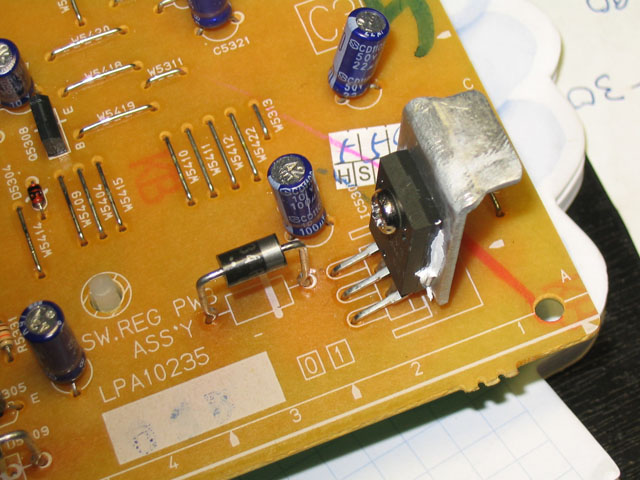
Besides, as I says before, I add a small heatsink to PQ5EV3!
-
Missed one. B5502.
P.S. That was a good effort with the heatsink but that small a heatsink will have little effect. -
5502 - have no jumper. )Originally Posted by trhouse
I know its not big heatsink but this was the one I have - better then nothing, and if the reason will be in PQ5EV3 then, I will buy bigger heatsink ! -
If you look at the silkscreen on the PCB where you put that heatsink, it looks as if the designer made provisions and room for it, but it was never added when the circuit board was built.

Or, maybe they thought they didn't need it, and the users are finding out otherwise.
-
The jumper information helped a lot. Can you measure the DC voltage across capacitor C5307 under these three conditions on/off/off power save?
-
I`ve got interesting results:Originally Posted by trhouse
On - 5,73v
Standby - 5,74v
Standby (powersave) - 5,77v
Also I measured temperature of some parts - D5309, D5310, D5305, Q5308
and PQ5EV3 - all of them are hot about +60C ! "Digital can" heated upto +45C ! I guess there is also about +60C under it ( -
The jumper information told me that all power to the dvd-ram drive and to CN5102 sheet 10 is off in power save mode. That leaves power only on CN5301 which goes to CN5101, sheet 10. The voltages that remain on in power save mode are -29V, AL-12V, AL12V, SW12V, SW5V, AL5.3V, 48V, 17V as described on CN5301 ( upper right connector, sheet 1 ). AL12V is what runs the fan so it is possible to run the fan even in power save mode.
The voltage you measured at about +5.75V is exactly correct. +5.75 is the calculated value from the parts used to set this voltage. The switching power supply only controls one voltage directly. This is the one. It should be very accurate and it is.
The temperature measurements are not good news. If your room temp. is about 23 degrees C. and you are measuring 60 on these parts then the temperature rise is 37 degrees C. The M10 is spec'ed to work from +5 to +40 degrees C. but at 40 degrees C plus 37 will be 77 degrees C. That will be very close to the max. rating for the PQ5EV3. The STR-G6653 has a large operating temperature range by comparison -20 to +125 degrees C.
The use of D5310, D5309, D5308 is to lower the voltage applied to the PQ5EV3. These devices absorb power that would otherwise be absorbed by PQ5EV3. The purpose of D5305 is similar. Transformer T5001 could have been designed to supply a lower voltage then these parts would not be necessary. It is hard to know the reason for this. JVC may be using T5001 is other products and want to use the same part for example. -
In other words, only 2 voltages - 1.8v & 5v are off in powersave mode - they are main power for digital board. I can tell you why I start checking digital board - I analyzied the sympthoms and found that those nasty green lines not only appers over screen but also can be recorded to disc, so this means that reason of such behaviour can be in LSI or video/in out controller. Also I waited when green lines cover all screen it looks like a rain drops from right side of screen to left (like shown on screenshots) and after a few hours of such work unit been resets itself - Loading appers on front pannel. It wasnt Loading problem like ppl described - it was LSI reboot because of bus errors - screen start destroying to block units (like when RAM fails). So I decided to chech power lines goest to digital board and find out its only 5v & 1.8 v. Thats why I start cheching this voltages. Also, this doesn`t affects audio.
-
From sheet 1, power supply section
The following connectors should have no power in power save mode.
CN5305 has 12V for fan off
CN5304 has DV12V, DV5V, DV3.3V, DV1.8V all off.
CN5303 has DV12V, DV5V all off
CN5302 has D1.8V, D2.5V, D3.3V all off
By digital board, I assume you mean from the manual "media processor" which is the DMN-8652. -
yes, exactly ! Btw, what for is 5.3v (5.7 in fact) ? I cannot understand.
-
Lordsmurf: Sounds like you have a personal beef with anyone complaining about this unit. Anyway, before you make blanket statements like "nobody ever complains of it breaking again," you should do some research. Check out this AVS Forum thread:Originally Posted by lordsmurf
http://www.avsforum.com/avs-vb/showthread.php?s=157b4a352f296e87ac34b6cf26210d9a&threa...g&pagenumber=1 -
Video Restorer
- Jun 2003
- dFAQ.us/lordsmurf
-
No, complain away. But be prepared for people to tell you "just because it happens to you, doesn't mean it happens to everybody". People pretty much only find this site because they have video problems or are new/confused, hence the saying "more complainers than not".
Until today, nobody had complained of it ever breaking again, so my research was perfectly sound. At this point, you should investigate whether or not they PROPERLY fixed it, that is to replace the power supply parts that are in question. Your paperwork should show what was done. Report back on it, let us know what's been done to it. Especially since some of the posters in this thread are actively trying to see what causes this issue.
My gut feeling is that, from reading you AVS posts, the JVC tech that FIRST "repaired" your unit messed up. Because the SECOND time you had them replace another part. Those resistors could be bad. I saw somebody suggest you do before/after shots of the "guts" of the unit. Did you do this? Maybe some half-ass tech botched it, or didn't do it at all (in the "repair" game, for any company, that's not uncommon).
I hope you also realize that crap media, and the associated read errors, will trip up the "loading" error, meaning it cannot load the media. That could be part of the problem too. What is the MEDIA ID of the discs you are trying to use?
There is NOTHING NEW in that AVS thread, and quite honestly, some really bad guesses and assumptions from some of the posters in that thread. JVC knows what's wrong, and they are fixing it. Unlike LiteOn/Panasonic/Toshiba/Sony and some of the others out there, where if you get a defective unit, you're just out of luck.
And BTW: Leave the attitude on your end of the keyboard this time. Forums are for helping each other, not attacking others (and therefore making it personal). Just present your information for open discussion.Want my help? Ask here! (not via PM!)
FAQs: Best Blank Discs • Best TBCs • Best VCRs for capture • Restore VHS -
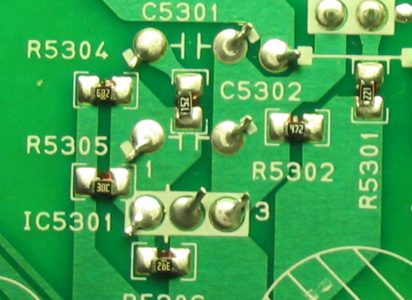
The +5.75V level is determined by four parts, R5304, R5305, R5306, and IC5301. Not sure why it is labelled AL5.3 on connector CN5301. It is a safe voltage on the power supply board since C5307 is rated at 10V.
What worries me is that AL5.3 goes to the system controller on sheet 12. There it goes through two small inductors, L3001 and L7201 to C7202 and C7203 which are rated at only 6.3V.
Do R5304, R5305, R5306 have a gold colored band on one end and can you measure the actual voltage across C7202 sheet 12? -
R5304, R5305, R5306- those are on sheet 1 ?
-
So, I measured voltage across capasitor C7202 :
standby mode - 5,71v
on - 5,69v
standby powersave 5,74v
About resistors - I don`t see any bands on them (
Here is the pic of them:
-
This is good information. First the voltage measurements indicate in power save mode that C7202 has +5.74V across it which is 91% of its rating. It is unusual but not fatal to the part to do this.
Do you see C3042 on the same sheet 12 ( left middle )? It is the same kind of part but the designer reduced the voltage to it by placing D3004 in series with AL5.3 which reduces the +5.75V to about +5V. C3042 is operating at 79% of max. rating.
It was disappointing that R5304, R5305, and R5306 are chip resistors. I was hoping to determine the tolerance of these parts. If we know the tolerance we can calculate the accuracy of the +5.75V. My concern is if the tolerance is too loose, the +5.75V might be able to exceed the 6.3 rating for C7202.
 Quote
QuoteSimilar Threads
-
HOT DEAL: St. Louis Craigslist - $75 JVC DR-M10 DVD Recorder
By jbd5010 in forum Off topicReplies: 2Last Post: 16th Mar 2011, 08:21 -
problem recording with jvc dr-m10
By restauroman in forum RestorationReplies: 3Last Post: 28th Feb 2010, 11:47 -
JVC 'loading' repair details
By Jack Africa in forum DVD & Blu-ray RecordersReplies: 8Last Post: 13th Apr 2009, 01:19 -
JVC DR-M10 help
By colt4523 in forum DVD & Blu-ray RecordersReplies: 1Last Post: 20th Mar 2008, 06:53 -
QUestion about JVC HR-S7600 repair...
By fireballtp in forum RestorationReplies: 5Last Post: 19th Nov 2007, 01:12