


trhouse, I noticed when I did a search for the Panasonic DMR-ES35V you have gotten your hands on one of these already and was wondering what you thought of the quality of the recordings against these JVC units ? I just grabbed one of these off Ebay for pretty cheap without a remote and haven't really been able to test it out until I get a remote. Whats nice is they record on just about all media +-r/rw and DVD-RAM and DL +-R . The only thing I found disappointing reading the manual is that you have to close the first layer of the DL disks before you can use the second. I noticed that they have their own proprietary drive in the unit it looks like which could be good or bad. Their regular combo
units have lousy reliability in their DVD drive which I have used. Also do you know of any recorders that have a digital zoom ?
+ Reply to Thread
Results 421 to 450 of 556
-
-
Is it possible that it had a heatsink and someone removed it? I would heatsink it if it were my unit and I intended to keep it. The LSI processor is the heart of the unit and expensive. A heatsink is very cheap insurance.Almost seems like a blatant way to cause an early failer of the unit.
The other possibility is that the chip uses different technology and does not get hot. For example, the processor in the Panasonic ES10 has no heatsink but it only feels slightly warm if you touch it. The DMN8652 and the processor in the ES35V get very hot by comparison and really need heatsinking.
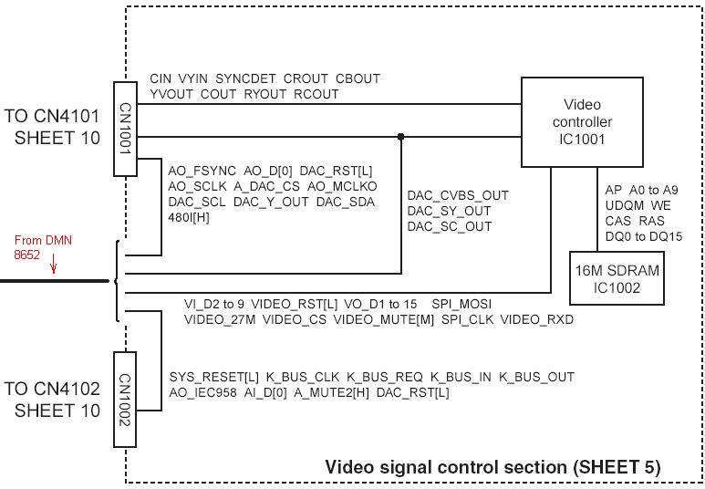
Here is the block diagram with the JSP8059. It is IC1001 described as the video controller.What is the job of the JSP8059 ?
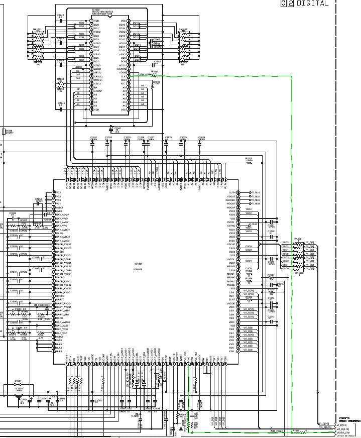
Here is part of the detailed schematic with this part. Hope this is not too confusing. I traced the path of the 27 MHz clock from the DMN8652 in green. There appear to be some resistors in the path to the JSP8059 but the values are zero ohms. I was not sure how legible those values might be. The top chip is the SDRAM which has a 470 ohm resistor in series with the 27 MHz clock.
I really cannot say yet. I do not own either of these recorders. A relative loaned me the ES35V because I am doing a big family project and from nearly the beginning the relatives were given samples of recordings made by various machines. By a simple majority, most preferred the Panasonic captures so I have been using them to create about 800 disks. I have had no failures with the ES10, ES30V, or the ES35V. The closing required for the first layer with the ES35V is certainly a setback if you want to record seamlessly across the layer change, but it allows me to put a number of clips on one side, close, and add clips to the next side thus avoiding the layer change altogether. No recorder I am aware of can do a seamless layer change. For that I use the computer.was wondering what you thought of the quality of the recordings against these JVC units ?
I have always been curious about the "loading" problem in the JVC partly because when I asked JVC directly what should be done if you wanted to fix one yourself, they would not answer. A friend shipped me this M10 because he is out of the country at the moment and he said it had both green lines and the loading problem. Since I received the unit I have not made any test recordings with it to compare against other recorders. It worked quite well when it arrived for more than a day with no sign of either problem, so I was setting it up to do a series of tests when the famous "loading" bug suddenly appeared. After that happened, I have been trying to locate the cause since it was recurring fairly reliably. It is not easy to troubleshoot because if you unplug it for safety reasons to pull a board out and start it back up again, the bug will decide not to appear for awhile as you well know.
The M10 has been running continuously for 48 hours now and still no sign of either problem. I unplugged it after 24 hours and changed to "power save mode" for the last 24 hours.
[edit] Almost forgot. The Sony RDR-GX315 I tested has digital zoom. It is the only brand I have tested with that feature.
-
Here is what I presently believe is the cause of the famous loading problem in the M10. Some of these comments only apply to US versions of the M10. I have found that PAL versions do not contain these parts and neither does the MV1.
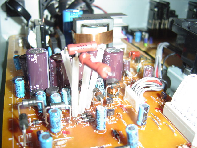
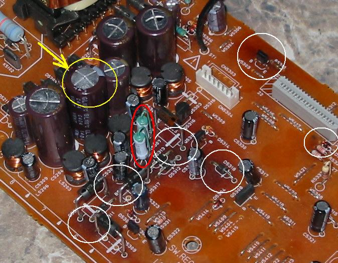
In examining the the power supply of this M10 which had both the green line and loading problem, I found these two resistors circled in red below,
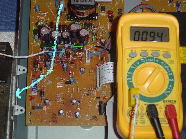
Even though Mig-45 did temperature testing, he never mentioned them so that is why I asked 4fuksake if his PAL unit had them. He said no. As you can see from the temperature probe held against one of these resistors ( they are R5307 and R5308 ) these resistors are extremely hot at 94 degrees C.
I thought these must be the two bad resistors we have heard about because they are two watt resistors dissipating only 0.37 watt. They are 390 ohms with about +12VDC across them. To test them, I removed them from the M10 and used an HP6205B power supply and applied the same +12VDC accross them.
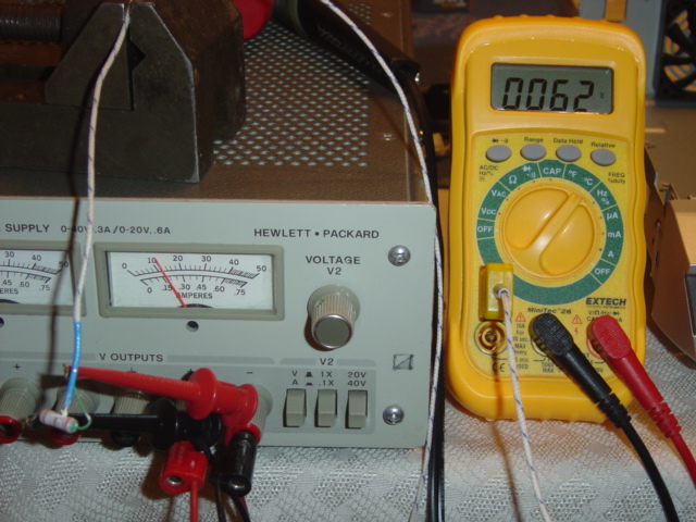
In this test, the resistors only reached a temperature of 62 degrees C.
I put the resistors back in the M10. Then with the temperature probe not touching but about 1/4" away from the resistors measured the air temperature. The air temperature was about 50 degrees C. even though the external ambient temperature was 23 degrees C. and the fan was operating.
What was found is that the row of vertically mounted electrolytic capacitors indicated in green effectively block the forced air from the fan ( indicated by the thick blue arrow ) to these parts. The air temperature measured with the probe an inch above the tallest capacitor was 30 degrees C. It is the 50 degree temperature of the air around these resistors which causes them to operate at 94 degrees C.
Most resistors can survive these temperatures ( with lowered reliability ) but the electrolytic capacitors surrounding these parts are only rated for a maximum operating temperature of 105 degrees C. These resistors essentially act little heating elements which are always on as long as the M10 is plugged in.
The temperature of these resistors was measured with the unit on ( 94 degrees C. ), off but not powersave mode ( 80 degrees C. ) and powersave mode ( 60 degrees C ). The explanation for this variation is that the +12VDC is not a regulated voltage. It goes up and down depending on how much current is drawn from the regulated +5V. The more current is drawn from the +5V, the higher the +12V on these resistors. I asked 4fuksake if he could measure the voltage at the location of these resistors in his PAL unit because when I removed them, the +12VDC jumped to almost +13VDC. I am not sure if that would have a detrimental effect on PAL units.
Here is how heat affects electrolytic capacitors
The loading problem is caused indirectly by these parts and can affect PAL and NTSC units. The fundamental problem is that the clock levels to the audio DAC and video controller are marginal from the DMN8652. The system controller apparently can recognize conditions when the clocks levels are failing. If the clock to the video controller becomes inadequate, the green lines can appear before the loading error, but if the clock to the audio DAC becomes inadequate, I think the loading error can occur without green lines. If green lines occur solely because of clocking problems there will not be increased macroblocks.The electrolytic capacitor uses aluminum-foil plates with a conducting semiliquid chemical compound between them. The actual dielectric is a very thin film of insulating material that forms on one set of plates through electro-chemical action when a dc voltage is applied. The capacitance obtained with a given plate area in an electrolytic capacitor is very large, because the film is so thin. Much thinner than anything practical with a solid dielectric. However, this also causes the breakdown voltage to be much lower than with solid dielectrics. The electrolyte is necessarily an acid; therefore it is extremely dangerous if heat builds up inside an electrolytic capacitor. It can bulge, leak and even explode. Look carefully at your higher quality electrolytic capacitors, and you may see a scoring mark 'X' at the terminal end which is designed to rupture and leak before the can explodes.
If another condition occurs such as experienced by Mig-45 in which green lines and severe macroblocks occurs, this seems to indicate the LSI encoder is overheating as only the encoder can generate macroblocks. Overheating of most chips will result in lowered output voltage levels which can then cause the appearance of lines.
How does the power supply create the loading problem and why would this be more prevalent in US units? I believe the answer is that all electronic components age including power supply parts. This causes the power supply voltages to change a bit over time. US units have these two very hot resistors which prematurely age the electrolytic capacitors which act as filter capacitors at the output of many of the DC voltages in the unit. I believe it is the changes in these voltages that alter the conditions between the DMN8652 and the other chips causing clocking errors which trigger the loading condition. So all units are susceptible but US units are more so.
The M10 I have been testing has now been operating continuously for 72 hours with no green lines or loading. I plan to test for at least 168 hours. The fix was the JVC factory modification of adding two 1K resistors to the digital board which boosts the output levels of the audio/video clocks from the DMN8652. -
Video Restorer

- Jun 2003
- dFAQ.us/lordsmurf


And the interior of the JVC DR-M100S is entirely different from the previous models, and that would explain why it is not susceptible to the loading problem.
Nicely done trhouse. Want my help? Ask here! (not via PM!)
FAQs: Best Blank Discs • Best TBCs • Best VCRs for capture • Restore VHS -
Glad to see the resistors look to have eliminated the green lines from your unit as well. . I do belieive like you said that the the electrolytics in the P.S are partly to blame since in standy by the temperature around them really goes up with the fan not on. What I did was to find another source to drive the transistor for the fan so it to comes on when it is in standby and when its on but have it off in power save mode.The increased noise isn't that bothersome for me. I think the main power draw in stand by is the LSI chip,maybe you can confirm this . I know the top of the metal container which contain the LSI chip gets really hot in stand by.
-
Thank you both for your comments.
It occured to me that if the MV5 does not have a heatsink on the LSI chip that might mean the M100 also does not since they are the same generation. Do you know which chip is in the MV5 or M100?
The DMN8652 is the chip that consumes the most power in the off, non powersave mode because it has four power supplies, +1.8V, +2.5V, +3.3V, and +5V, and does get hot, but the assembly consuming the most power is the power supply.
The reason for this is that aside from the +5V switching supply which is very efficient, all the other other regulated voltages like the +1.8V are produced by linear regulators which are not very efficient.
For example, suppose the +1.8V is derived by regulating down the +5V and suppose the LSI draws 1A from the +1.8V supply. The regulator consumes roughly ( 5v minus 1.8v times 1A ) 3.2 watts and the LSI only 1.8 watts ( 1.8v times 1A ).
96 hours and the M10 is still going. I kept a record of how it entered the green lines and loading states. While watching TV, lines would start a few at a time, get worse, and eventually the loading message would appear. It was also fairly common for the loading message to appear just by having the dvd tray open. None of these conditions have reappeared.
I am actually doing a cycle of 23 hours on, one hour off, non power save mode, 23 hours on, one hour off in powersave mode, and repeat. -
That is great work! I have yet to get mine fixed by JVC because the closest service center is 2 states away and I dont have the money to ship it as opposed to just unplugging it after I do my usual 6 hours of records.
But my father in law ran a tv/vcr/electronics repair shop for over a decade and has agreed to help me do what you showed above, worst comes to worst I just put back in the old resistors and tell JVC it does not work 8)
Thanks again for your findings! -
Good luck with the two resistors. They cost me $.11 for both with tax.
The temperatures here soared to 90 degrees F. today but after 120 hours of continuous operation with one hour off every 24 hours, it is still good. If it passes 48 more hours, the owner owes me a nice dinner. -
Member

- Apr 2004
- Death Valley, Bomb-Bay
-
I Never had a Problem with my DRM-10 but the Loading Bug finally hit my machine, it won't go off. Even Cut power. Had to Email JVC for help. I don't think its still under warranty. So I might get screwed!! Great information on this post but nothing to aid me. It has it be in the power supply or microprocessor. I love the DRM-10 its still a great machine but those chinese parts are a killer.
-
I thought the "loading" bug is not considered a warranty repair but more of a recall in the US for a known defect. When you email or talk to JVC, you might want to mention that it is discussed on their web site in the faq's that the repair is to be free.
Is there a reason you think your loading bug is unique or did you mean you prefer not to open the box? -
Here is one solution to cooling R5307 and R5308. I replaced the 390 ohm, 2 watt resistors that came with the unit with these larger ones which are still 2 watt. The advantage is that the larger surface area of the resistors allows them to get rid of heat faster.
The resistors are mounted on wire leads covered with heatshrink tubing. The tubing is not shrunk in the photo to make it more visible. The wire leads are long enough so the resistors are above the tallest capacitor and in the path of the forced air from the fan. Their body temperature is now about 60 degrees C. instead of 94. Even when the fan is off, the heat generated by the resistors remains mostly above the capacitors to prevent heating these parts.
-
Member
- Apr 2004
- Death Valley, Bomb-Bay
-
Trhouse, I don't think my Loading Bug is unique. It just happen very weird. I play a movie 16 Blocks. When to pop some popcorn can back Loading Bug Blinking. Very Odd, Got the Movie out By opening Casting etc. I did try thr Freeze spray( didn't work). The DRM-10 gave me good service until then. I hope JVC will fix or replace it that would be a great gift. But they probably charge like $100 day and hour to fix it..I prbably will have to get another, this time extended warranty? Thanks
-
Marvingj,
The loading bug was identified in my July 19th post as being caused by marginal clock levels between the DMN8652 processor and support chips. The solution was to add two 1K pullup resistors to the digital assembly. It appears to be the factory solution. There is a photo of the fix in jethro12's post of May 12th.
The photo was originally posted by enlsnws. At the time, enlswns was suffering from overheating of the LSI processor. No one realized that his photo contained the factory fix for the loading bug until jethro12 mentioned it again. I was able to determine what those resistors were for with the help of the manuals supplied by enlswns and Mig-45.
I used this fix on an M10S with both green lines and the loading bug. The unit has been on continously now for about 160 hours. Neither problem has recurred. I am testing for 168 hours ( seven days ).
[edit]My July 15th post shows a schematic of what those factory added resistors do. -
The testing of the M10S is now complete. 168 hours of 23 hours on with 1 hour off in either powersave or non powersave modes for seven days. The green lines and loading message never appeared again. The last two days the temperatures in the room reached 90 degrees F. and the unit remained solid.
Thanks to Mig-45 and enlsnws for the many discussions and manuals. Thanks to Lordsmurf regarding resistors and jethro12 for pointing out the factory solution in the image posted by emlsnws. All these contributions eventually led to uncovering the loading bug which turned out to be marginal clcck levels between the DMN8652 processor and peripheral chips aggravated by voltage drift due to premature aging of filter capacitors in the power supply caused by two resistors getting too hot from blocked air flow ( these two resistors are only in US units but not PAL units or MV1's ). A nice puzzle it was. -
Member
- Apr 2004
- Death Valley, Bomb-Bay
-
THANKS TRHOUSE, I WILL TRY THAT.
-
Hi Guys,
My DR-MV1 (which is out of warranty) developed the loading fault a few months back. Rather than bin it or flog it for next to nothing (cause I have not much diy skills) I put it in the spare room and have been using it successfully with power save mode on.......Until the other day when whilst recording to a DVD-R (with a brand I never used before) it went into the loading cylce. Only when i unplugged and turned it back on the loading appears briefly before all lights go out only and then unlike usual I am unable to turn it on. None of the buttons react. It simply flashes for a minute then goes off.
Is it dead or can I boot it back up somehow?
any advice would be great. -
Member
- Apr 2004
- Death Valley, Bomb-Bay
-
Instead of fixing myself I sent it to JVC, they fix the loading bug & gave my a new drive. JVC is still kind to the Customers. My DRM-10 works like a charm. What a Great Day!
-
Hi All,
thanks to the info gained in this forum I've managed to get a new DR-M10 from JVC UK. After I got the "Loading" error, the customer service was initially very poor (no response to voicemails, poor information etc) but I persisted. I was told that JVC UK is a different company the JVC US and that they haven't accepted an inherant manufacturing fault with earlier models. They also tried to shift responsibility onto my seller as I purchased the unit off EBay. However, I quoted the info here and finally got in touch with the british manager ( Kris James, tel 0208 4503282 then # then 2 then 5263, Fax 0208 2087655) who agreed on a replacement as a guesture of goodwill.
thanks all for your help! -
Hi all I have just finished reading all 15 pages and wow what a quest it has been. Many thanks to all that have spent hours trying to fix the problem with players / recorders
So now here is a new one. Does the mods apply to:
DR-MH50S - dates of dvd drive march 2005 serial: 080B0459 unit is PAL. Made in germany
DR-MX1S - dates of dvd drive march 2005 serial: 080B0165 unit is PAL. Made in germany
The dsp board is different to that of the pics shown but the are no resistor mods and the area where the mod is to be done is the same (see pics)
For both the recorders the problem is once the pulg is turned on the loading flashes on the LCD on the player, no output to the TV screen.
I will post in a bit all pics of psu + digi board.
Any help will be much welcome + i have a good eng background so have no probs with the tech terms
Sam
Added pics:


-
I am doubtful that your loading problem is related to the famous one with the M10S. The power supply board in your units looks different and the digital board assembly is LPB10247 vs LPA10236 for the M10S board. The digital board also looks like it has been redesigned.
The problem is that the loading flashing covers a multitude of ills including bad media so this question may related to an entirely different issue.
P.S. Nice photos. -
Many thanks for the reply trhouse. I thought as much once I had seen the boards myself but posted on the off chance that I may have missed something
Well as media goes, the DVD drives are empty so no read errors there. However the HDD could be at fault. Since this was the main suspect I connected it to windows via an external USB case and found the file system is not a windows type i.e. Fat or NTFS etc... So then I guess they have their own version. But looking at the HDD it looks like a normal drive hence would it be possible to replace the drive with a PC type one and have the player format it? Or would it be a case of doing the prep work before installation is the golden question I guess.
If anyone else can point me in the right direction I would be grateful
Thanks in advance
Sam -
I upgraded the hard drive in my Pioneer 531H from 80 GB to 500 GB. There is a thread about how to do it. One important item is that the Pioneer service manual describes how to replace the hard drive. The JVC manual might do that too.
Were you able to see the drive in the external USB case? I plugged my old 80 GB hard drive from the Pioneer into my computer and it did not see it, but with a program called sectedit, I could see and read the sectors on the drive in Windows. Here is a link to sectedit,
http://www.roadkil.net/Sectedit.html
It appears that Pioneer uses a version of Unix for the operating system. I suspect JVC might also since Unix is very stable.
With the Pioneer, replacing the hdd is pretty involved because they have the TV Guide and timer functions residing on the hdd. They also have a CPRM ID number assigned to the hdd. If the hdd is unplugged from the recorder that information is lost and has to be re-entered using a special service remote. As soon as I removed the 80 GB hdd and plugged it back it, the display said HDD ERR until I reprogrammed it with the service remote.
[edit] Here is a thread in which Tangerine replaced his JVC hard drive. It sounds easier than the Pioneer,
https://forum.videohelp.com/viewtopic.php?t=308371 -
Hi Guys!Originally Posted by trhouse
Does anyone have suggestions for fixing the LOADING problem on an Australian PAL version of the M10S?
Mine has suddenly started going into LOADING flashing within a couple of minutes of doing anything disc related - ie formatting a disc, playing a disc. The unit does feel warm on top even after only a couple of minutes of being powered up. I haven't yet opened it up to look at the resistors, capacitors that have been mentioned as suspect - am a little confused about what's relevant to a PAL model compared with an NTSC model??!??
Thanks in advance,
Paul. -
The fix to the digital board applies to your version. This is a factory fix first identified in a UK PAL unit. US versions are more susceptible than PAL versions due to power supply resistors that run very hot. PAL versions do not have those parts.
If you do not want to try this yourself, call JVC support in Australia and see if they will repair this problem out of warranty. They will in the US. I know a person who just sent a unit manufactured in 2004 in to a service center and it was repaired for free. -
OK so this is the addition of 2x 1k resistors? I did contact JVC Australia - after 2 weeks they replied that if I took the unit in to their service agent - they would consider how they could help based on the assessment - ie I could be up for $$$ just for the review and they still might not help. For the costs of a couple of resistors I"m willing to give it a crack - I'm pretty handy with a soldering ironOriginally Posted by trhouse
Thanks again,
Paul. -
Ah, no, not necessarily. The 1K resistors are really for the green line problem. I have the NTSC version that went in for repair over a year ago for both green lines and the loading problem. JVC added the 1K resistors and also replaced the power supply capacitors, upgraded to larger sizes with higher voltage ratings. The recorder is again giving me a loading problem (no green lines), but this time it is strickly due to the power supply. I will be submitting a more detailed post in a few days explaining what I found. The short version is that a power supply capacitor failed (one of the JVC replacements).Originally Posted by psmedley
Does your unit also have the green line problem? If so, then yes, you will need to add the 1K resistors. If your unit has only the loading problem, then the power supply is probably the culprit.
MGY -
The "loading" problem can cover a multitude of ills but the two resistors do cover a case where there are no green lines but the loading problem still occurs.
The two resistors are for two separate issues. One is to increase the video clock level. If this level is low, there can be green lines. The second is for low audio clock levels. If this is the problem then there will be no green lines.
Green lines are created by missing clocks which present the same data to the memory chips repeatedly.
One way to tell if the problem is likely to be solved by the additional resistors is does your unit intermittently work ok such as after unplugging it? If it does then it is a good candidate because the problem with the clock levels is that they are marginal not that they are failed so it shows this intermittent behavior.
[edit]As noted above, US units are likely to show more power supply capacitor problems due to the two resistors on the power supply board operating at 94 degrees C. The electrolytics are only rated for 100 degree C operating temperature but PAL units do not have these. -
I opened up my unit this evening - appears my digital board already has the two resistors added to it.....Originally Posted by trhouse
-
The person who had a "loading" problem and had the resistors in his unit already in the UK found that the thermal pad to the LSI processor on the digital board was not making contact with the metal can which acts as a heatsink. This caused the LSI part to overheat.
This can be fatal for the LSI processor so I would check that next. After that I would look at the power supply especially the electrolytic capacitors for any signs of bulging or leakage. The capacitors have little lines scored in the tops to let out gases so they do not explode if they overheat. Sometimes a brown liquid will ooze out of the top when they go bad. -
To trhouse:
First and foremost, I don’t want to start an argument, especially when it is obvious that you have more experience with the DR-M10 problem than I have and most especially when I agree with everything you have said. By the way, I very much applaud your posts in this thread; truly excellent research. Thank you.
TO everyone else:
My DR-M10 was made in Japan, May of 2004. I sent it in over a year ago for the green line/loading problem. It worked fine after that until two weeks ago. Since it is now out of warranty, I opened up the unit and took a look. This is my power supply board:
Note the heat damage in the areas circled in white. Trhouse is correct in that the two power resistors in the NTSC model (R5307 & R5308, circled in red) do generate quite a bit of heat.
Power = (12 volt)2 / 390 ohm = 0.369 watts (in each resistor)
But the RK34 Schottky diodes and the zener diodes also generate quite a bit as well:
Schottky Power = 0.5 Amp (average) X 0.6 volts (forward drop) = 0.3 watts
Zener Power = 12 volt X 0.025 amps = 0.3 watts
And there are a lot more of them on the board. Some of the worst heat damage on my board is associated with the diodes. If the PAL units have a power supply anything like this, then heat can still be a problem, even without resistors R5307 & R5308.
Trhouse is correct about the capacitors. If you see leakage or a bulge on top, then it is probably blown. However, the capacitor CAN go bad without any bulge or leakage showing at all. Note the capacitor circled in yellow. It is hard to tell in the photo but this one has a very small bulge on top. So small that I missed it until I was checking the voltages in that part of the circuit and discovered that they were much lower than they should have been.
Also please note that my unit did not die suddenly. When I first saw the loading problem two weeks ago, I unplugged it for two hours, plugged it back in and everything worked fine – for a few hours. And then the loading problem came back. I repeated this process three times – with decreasing effect each time. So it is possible (though not likely, I admit) for a bad capacitor to produce a similar effect to a low clock line.
So, if you check your board, the first thing to do is closely examine the capacitors, especially C5202, C5203, C5204, C5207, C5208 and C5209 for damage. Then check the diodes in-circuit. All of them. A good DVM will allow you to do that without unsoldering the diode. Check output voltages. I honestly don’t know what the configuration of the PAL unit looks like but in the NTSC version pin 2 of IC5302 should be 1.8 to 2.0 vdc. At connector CN5101 there should be -29 vdc at pin 3, -12 vdc at pin 4, +12 vdc at pin 6, +5 vdc at pin 11, +5.3 vdc at pin 12, +3.3 vdc at pin 17 and +48 vdc at pin 19. If any of these voltages are low, then you have a power supply problem. Assuming that one or more voltages are low, unsolder and pull the capacitors. If one of them is bad, be careful what you replace it with. If possible, use a capacitor with a higher voltage rating. And in this power supply, don’t use one unless it is rated for 105 degC.
There are 3 main weaknesses in this power supply design:
1. With the exception of IC5302, most of the heat generating components are all tightly packed together. Not good.
2. The large filter capacitors, transformers and such block the air flow from the ventilation fan at the rear of the unit.
3. The ventilation fan does not operate with the unit turned “off” even though the power supply is still operating. (I verified this after repairing the unit.) Thus the unit can cook itself in its own heat when you think it is turned off!
Also note, that just because JVC may have “fixed” your unit once doesn’t mean the loading problem won’t come back.
Bottom line: Please be careful where you put this recorder. It needs as much ventilation as you can give it.
I hope this helps.
MGY999a[/img]
 Quote
Quote


Similar Threads
-
HOT DEAL: St. Louis Craigslist - $75 JVC DR-M10 DVD Recorder
By jbd5010 in forum Off topicReplies: 2Last Post: 16th Mar 2011, 08:21 -
problem recording with jvc dr-m10
By restauroman in forum RestorationReplies: 3Last Post: 28th Feb 2010, 11:47 -
JVC 'loading' repair details
By Jack Africa in forum DVD & Blu-ray RecordersReplies: 8Last Post: 13th Apr 2009, 01:19 -
JVC DR-M10 help
By colt4523 in forum DVD & Blu-ray RecordersReplies: 1Last Post: 20th Mar 2008, 06:53 -
QUestion about JVC HR-S7600 repair...
By fireballtp in forum RestorationReplies: 5Last Post: 19th Nov 2007, 01:12