


Not sure if anyone is still following this thread but I bought a used DR-MV1s which worked for about a week then began getting the green line phenomenon really bad to the point it was only usable for an hour or two even after letting it sit unplugged for a day .It would also turn itself on randomly and go into the loading cycle . I came accross this thread which had some really helpful info.
Emlsnws posted some pictures of the underside of his Digital Board which looked to have a modification that mine didn't have which were 2 resistors which he measured at 1000 ohms each . I had already adjusted the 1.8v line and put a thicker thermal pad but it didn't do anygood. Well I figured I had nothing to lose by trying the modification and so far it has been working for 18 hrs straight with no green lines . My manufactured date is June 2004 for this unit . Below is the picture of emlsnws's digital board which I used for the mod. It's still early on so I don't know if the mod is going to be successful in the long run given that alot of people have had to have theirs fixed multiple times and still had problems but so far so good.
img_4925.jpg
+ Reply to Thread
Results 391 to 420 of 556
-
-
I have a civilian friend who works for a defense company going to Iraq this week. He says he has a JVC DR-M10S with both the loading and green lines problem so he shipped it to me this week to see what can be done. I will post what I find regarding either issue.
-
Hi,
Just for those interested.
As a novice to DVD recorders and HHD units i purchased a brand new JVC DRMH-30S less than 3 months ago, and on Friday night it developed the 'loading' issues mentioned on this group.
My fault manifested itself whilst deleting a file from the HHD, but has since started to do it again either using the HDD or copying onto DVD.
This is a UK unit ,presumably made in Germany.
Whats particularly gauling is that JVC has their #300 unit out now and its way below the price i paid for the -30S. Still luckily under UK law i am entitled to a full refund if i can prove it was known that the item had fault issues that JVC knew about and subsequently the Vendor should have known about on an item under 6-12 months old.
Will post when i get some news.
Dave -
Hi Guys, I am in France and bought a DR-MV1S from ebay UK last year. It was described as boxed as new, fully working, blah, blah, blah. Anyhow it had the dreaded loading fault. Sent it to JVC and got it fixed for about 95 euros including postage. Now it has developed another fault. When I switch on it does the normal loading, all OK, goes to satnd-by with clock on etc. Then after about 3-5 mins after switching on, "click" it switches off completely, no life at all. Have to unplug and replu. Loading, stand-by, reset clock etc. Might be lucky and get 10 mins or so then "click" switch off again.
Any ideas on tis one? Id on't feel like spending out on it again. maybe a home fix. Have opened it up and blown all dust out etc. Still same.
thanks in advance. -
further to my last posting JVC wrote to me and offered to swap out my barely off the shelf NEW unit of less than 3 months age, for a second hand 'repaired' unit.
Good deal huh? NOT!!
I politely declined their offer and managed under the UK 'sale of goods act' to get a full refund from the store i bought from.
for those that dont know, if its les than 6 months old the revised law says that if it was sold with a known issue/ fault your entitled to your money back. The fact that the Store or apparently JVC UK didnt know about this seemingly worldwide fault is neither here nor there.
Ker ching into my back pocket , and to think i hate this government for their rules. lol -
Hi to all!
trhouse - thanks for you help!
Long time no posting - I finaly solve my DR-M10 problem in one of service centers - they have info how to fix "green line". there was an issue on old DR-M10/ MH30 models with CPU voltage - LSI chip become damaged - while unit goes power on from standby mode some nasty voltage picks appers on power lines and often damage LSI. In recent revisions there are additional filters made to avoid this problem.
Now bought DR-MH300S - cool thing btw )) -
Hi Mig-45,
Glad to hear the problem was solved. After all your efforts, it almost had to be a damaged LSI chip . Thanks for posting that voltage spikes are what damaged the LSI. I am going to receive a M10 soon which is supposed to have both the loading and green line problem. I will check for voltage spikes and post any results. I am told it is a July/2004 unit. -
Hi, I've been watching this stream for a while with great interest.
I'm in the UK with the PAL version of the DR-MV1S - unfortunately mine was fine for ages then the loading messages started and the digital-side picture started "green lining" (after the white dots and lines !). VCR fine ! By the time I tried to do something about it, I was too late and warranty had expired. JVC in the UK just were not interested. I tried to get a price from them to have my unit repaired with these known faults - but they wouldn't even provide a price. Basically, they'd only exchange the faulty boards on those under warranty or those under 18 months old with the original purchase receipt (which I've lost !).
To move forward, I've followed the some of the suggested fixes - replacing 2 x capacitors and 2 x resistors. Having spent a considerable sum on the unit, I didn't want to just bin it if there was a chance I could get it working
I performed the component changes in stages to see the effect.....
Firstly, replaced C5207 with 4700uf 6.3v capacitor - that fixed the "LOADING" problem, but still had bad screen.
The following week moved on to the resistors - replaced R5501 and R5502 with 560 ohm 0.5w. Then the "LOADING" came back again
- so the following week, replaced capacitor C5206 - again with 4700uf 6.3v - et voila ! Everything looked great (for a while !).
Also, following another suggestion think I found on here, have drilled holes in the outside cover above the power board to provide extra ventilation.
Originally, my screen would start white-dots/lines almost immediately and be totally un-watchable after 20 mins. After the above changes, PERFECT picture for hours. However, after days of having the unit working fantastically, I'm back to the green-line scenario where the picture gradually gets worse. At least I don't get the white dots/lines - so must be moving forward. The picture actually stays OK for a while before the distortion starts, unlike the white-dots appearing immediately.
I'm no electrician, but happy enough to change parts on boards - some of the technical discussions went over my head, but I had obviously picked up on the C5206, C5207, R5501 and R5502 changes.
Anything else to try ?? (apart from bin the unit and buy another)
Cheers. -
Have you checked the the LSI processor to see if it the silicone rubber, thermal pad is making good contact between the LSI part and the cover? That is the source of green lines.
-
I have had one of these DR-M10S Pal units for about 18 months and it only ever played up once - until now - and I live in the tropics, never had power save mode on or had it properly ventilated and it looks like I now have to pay the price, it is now "loading" constantly. I can not see a date on it but I would assume that it is a 04 model, made in China.
After reading most of the technical comments housed within this forum I thought I would throw my two cents worth in. I have a technical background but I'm afraid I've forgotten too much to help much but looking at the power card I see plenty of heat on the card around the previously mentioned STR-G6653 (IC5101), also around D5310 and Q5310/R5310. R5328/5327 look ok. Caps. C5208/5207/5203 look to have their lids raised a bit but have not leaked. I pulled R5310 out - it's chipped but I think it should be 820ohms, I measure it as 9ohms. The SMD's underneath Q5310 are beyond my equipment/skills/eyes to check.
Does Q5310 do anything related to our problem and can it be tested to see if it has also gone ?
Which pins do what on IC5101 to check it's operation also ? -
The service manual says R5310 is a 8.2 ohm 1/4 watt resistor. Here is a link to the datasheet for IC5101 ( STR-G6653 ). The 6653 is the 120 watt output version of the 6651.
http://www.datasheetarchive.com/search.php?q=str-g6653&sType=part&ExactDS=Starts
Please be careful around this part. The voltages are high and dangerous.
Just curious but does the PAL version of the M10 have resistors R5307 and R5308? The reason I ask is because I have a photo of the power supply board which shows these parts are not there ( the spot where they should be is labelled ), but they are on the schematic. These are 2W resistors in front of the row of tall electrolytic capacitors near the middle of the board.
Q5310 is a switch which turns on or off a voltage labelled DC3.9(+). The schematic indicates it will change states when PowerSave is enabled but will be on otherwise. -
Ah ok R5310 is 8.2 ohms that makes sense. gold not brown. The only affect so far installing the 820 was making the vdu not work ? I better put back the 8.2.
No R5308/5307 are not installed.
tar. -
thanks trhouse for your response - probably a dumb question - where's the LSI chip please ?
-
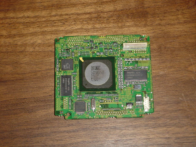
The LSI chip is located inside the metal container underneath the DVD drive. To get to it you will have to remove the metal container . While the thermal pad is a weak area it had no affect on my green line problem .Originally Posted by icouldrey
My unit was bought off Ebay as a project. The seller said the only problem was it stopped playing in the middle of movies and shut off.I had no problem with it for the first week of use then it began getting the green lines and shutting down. If I left it on long enough the whole picture would dissappear like when you loose reception from a transmission. Mine became unuseable because I could only have it on for 2 hours or sometimes less and the the green lines would appear and it would shut down. I could unplug it and it would be ok
for awhile but basically it became useless because I couldn't set it up for timer record because the LSI chip is online even in standby(Why JVC?) . Anyways I noticed a mod. on the digital processor board that someone posted that mine didn't have which were two 1000 ohm resistors . As I said in the other post I had nothing to lose so I modded my board and it has been running perfectly since. I don't have a schematic for the digital board so I am not sure why it solved the problem. I do run my unit in power save mode when I am not recording a show but I am going to test it without being in power save mode for a couple weeks to stress test it. If that works out I am going to mod my other unit I have which was manufactered at the same time and while it doesn't have the green lines yet I beleive it is only a matter of time. It does have instances in which it randomly turns itself on and goes inot a loading cycle just like the other unit.
Now I wouldn't suggest doing it unless you have no other options because I paid very little for the unit and had little to lose . My unit was manufactered in July of 2004 . I also know their are different revisions to the Digital processor board but I don't remember off hand what the one in my unit was.
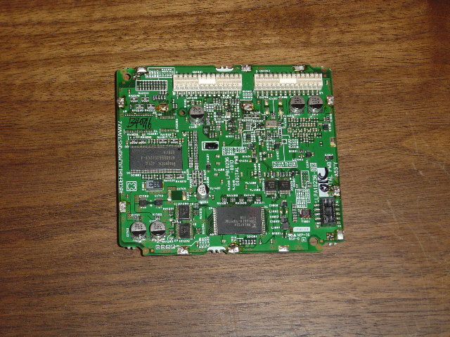
Below is the picture of the mod. and I circled each resistor involved and a marking on on each resistor that I soldered the 1k resistor between these points. On the right most 1k resistor I had to kinda guess which resistors were involved because I couldn't quite tell because of the blurriness and lighting and the resistor itself obscured the picture.
Now this mod worked for mine and I can't say for sure what it will do for anyone elses
given there are different revision so don't blame me if you try it and it doesn't work or worse I would only try it as a last resort . This is not my board but some none else that posted this previouslythat had removed theirs. Unfortunately my camera doesn't have enough zoom for me to clearly show how I modded it.
img_4925a.jpg -
Do you remember the reference designators ( example, R5111 ) for the resistors that you changed in the MV1 to 1000 ohms or were these resistors added to what was there already?
Also do you remember where the fix was posted? I have the schematic so it may be possible to explain why the fix worked.
The DC3.9(+) only seems to go to the display board along with DC3.9(-) and +29V. Can you measure the voltage that is at location of R5307 and R5308. If you have a voltmeter, just poke it into the holes that were left when these parts were not loaded. It is a positive voltage relative to ground. -
Actually these resistors weren't actually on the unit that I had and were added later I guess to fix the problem I am assuming. I posted a picture above and showed the mod that was done which I followed .Originally Posted by trhouse
Someone on this board posted the picture of thier digital board and I just noticed that my board didn't have the resistors like his did and he measured them and said they were 1k resistors. I then remember reading elsewhere that there was a fix with 2 1k resistors so this looked like the fix .
I am going to do the mod to my other unit in a week or so but right now all my units
are assembled so I can't check the voltage for you at this time but I will when I mod it.
I measured the resistance between both connections before adding the 1k resistors and it was basically an open circuit between both points on each .
The original poster of the picture was "Emlsnws" in this thread if you look through it. -
Originally Posted by 4fuksake
It's most likely the caps especially if they are bulging on top from overheating but could
also be something else but I would try the caps first. I have fixed other JVC models in which the caps had gone bad . You could check the secondary voltages to see if they are low where the bulging caps are . -
I worked with emlsnws quite a bit but do not remember his making this modification. He lowered a power supply voltage AL5.3, improved the heatsink contact to the LSI chip, and increased air flow to the entire unit by drilling holes if I recall correctly.
A search for that image file did result in any hits except for the one occurrence in your post assuming you did not rename it.
It is pretty hard from the photo trying to see which points they are connecting together with those 1K resistors. It looks like the leftmost 1K is connected between a 100 ohm and a 1K resistor. The K1011 through K1013 are jumpers.
It harder to tell with the rightmost 1K. Is it connected between two resistors labelled "101" ( it means 100 ohms )? There is a red dot over the top connection obscuring the last digit in the value. -
Originally Posted by trhouse
I had to find his posting again,it is on page 6 of this thread and posted on May 24,2005
I probably did change the picture name.He has three pics in his message.
I think when he was modifying his case and fixing the thermal pad he mentioned that his Digital Board had those resistors and that they looked like a mod to him. His problem was the loading bug but as he mentioned he never had the green lines phenomenon which is probably why . I noticed that mine didn't have it .
The rightmost 1k resistor is connected to the two (101) 100 ohm surface mount resistors. The resistors don't seem to have any id markings on the board for them that I could see . Maybe the schematics have the layout and the #'s ? -
I will look into it later tonight and get back to you. It is true, emlsnws never had the green lines. I misunderstood about how the change was made, that it was a factory fix not what emlsnws did.
P.S. I was actually asking 4fuksake to measure the voltage at the place where R5307 and 8 normally would be loaded. I would expect that without these resistors, the voltage at that point will be higher than normal, but I would be curious just how much higher it is for a PAL unit. -
The manual does not have a layout drawing of the board and the board does not seem to have reference designators for the parts to which those 1k resistors are attached.
The good news is that the M10 uses the same p/n board ( LPA10236 ). I now have an M10 so I should be able to determine what JVC did.
This M10 is said to have both the green lines and loading problem. The manufacture date is July/2004 so it should be the same vintage as your combo. I expect not to find those resistors but we shall see.
[edit] Thanks for posting the date of emlsnws's photos.
[edit] I now have the digital board out and it has the same p/n 10236-02 as emlsnws's but the two 1K resistors are not there.
[edit] The purpose of the leftmost 1K resistor added by JVC seems unrelated to video. The DMN8652 processor has an output ( A0_MCLKO ) which goes through the 100 ohm resistor in the upper left of the picture. After the signal goes through the 100 ohm resistor, the 100 ohm is tied to the +3.3V power supply via the 1K resistor added by JVC. This signal is the clock signal for the 24 bit audio DAC. The DAC requires a minimum of +2.2 V for a high level. The added resistor appears to be just a pullup resistor to assure the +2.2V high level will be reached.
To find out what the second 1K resistor does, I may have to unsolder the metal can from the board. The DMN8652 has a lot of 100 ohm resistors connected to it. I suspect those two 100 ohm resistors connected with the second 1K resistor relate to some other DMN8652 function. -
This will take a bit longer than expected. The board came out of the can readily enough but the DMN8652 does not have exposed pins to probe. I can see the pins by looking underneath the lip of the chip so I need to fabricate a little probe thin enough to to slip under it to see to which pins those 100 ohms are connected.
These images are not as sharp as emlsnws's because they are VGA resolution for posting to this forum. -
Yeah thats gonna be pretty tough to trace if it is under the chip unfortunately. Do the schematics have the pin functions so it can guide you ? I went to LSI's website to look for some info but they didn't have much other than a modular breakdown of what the differentOriginally Posted by trhouse
units within the chip did. -
Yes, the schematic has all the pinouts but no description of what they do. I can deduce what they do via the name and by following them to what they control, drive, or the part from which they receive data.
Here is a sample which includes the output A0_MCLKO clock for the audio DAC with the 100 ohm resistor ( R1478 ) that is being pulled up to +3.3V. One side of the 1K resistor JVC added is +3.3V ( the side connected to the 1K chip resistor ) and the other is connected to the top of R1478 in the figure below,
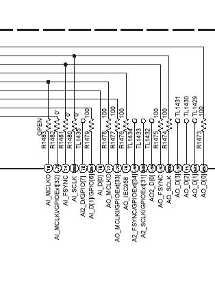
I am going to make a little wire probe so I can feed it under the lip of the LSI chip. I can see the pins pretty clearly. They are about 3/32" past the outer perimeter of the chip. I believe this is a 100 pin chip and I can count about 25 per side so they are not layered which would make it really difficult. -
I made a wire probe and was able to identify all the connections for the two 1K resistors added by JVC. Here is schematic of what they did,
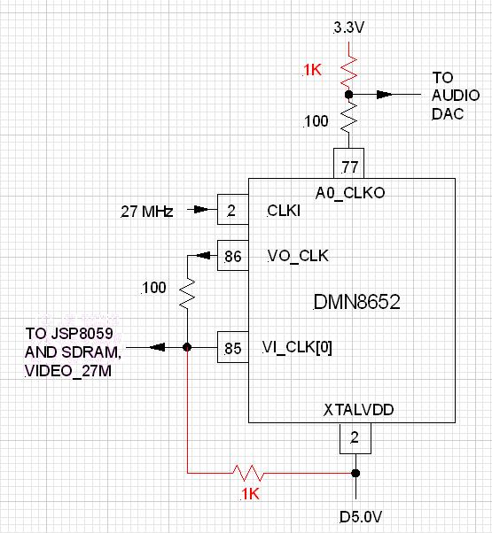
These resistors are what we call "pullup resistors". Their purpose is the boost the output high voltage of both the clock signals from the DMN8652 chip. Most of the time the DMN8652 drive seems adequate but JVC must believe that under some circumstances the 27 MHz clock and audio clock signals will not have sufficient amplitude to drive the audio DAC, SDRAM, and their custom chip JSP8059. It is not uncommon for chips to have reduced output when they get hot. In this case, the DMN8652 drive must be a bit marginal when it gets hot.
I plan to try JVC's fix on this M10. It does get green lines. The M10 is set up with no disk. I can be watching TV though the M10, suddenly green lines will appear and after awhile the "loading" message appears.
I think we are close to identifying most of the sources of the famous "loading" problem including why US units are more affected than PAL units. -
Great job tracing the connections. Yeah it looks like the second 1k resistor is more of the fix to the green lines. Is pin 86 the Video Output Clk signal and are you saying that this was maybe low and then the 5v boosted the signal to the proper level?
Let me know how it works out after you apply the the mod. -
Yes, there is a separate clock chip that generates the 27 MHz that goes to pin 2 of the DMN8652. The DMN8652 redistributes it. Pin 86 sends it back out to pin 85, the JSP8059 custom chip, and a SDRAM chip. The clock is typically a square wave with a high and low level. Adding a resistor like that is often done if the high level is marginal.
Adding those resistors is not childs play. Those 100 ohm chip resistors are very small. It is easy to remove one accidently, which I did, but it is now back in place. The M10 is reasembled with the JVC fix and being tested now.
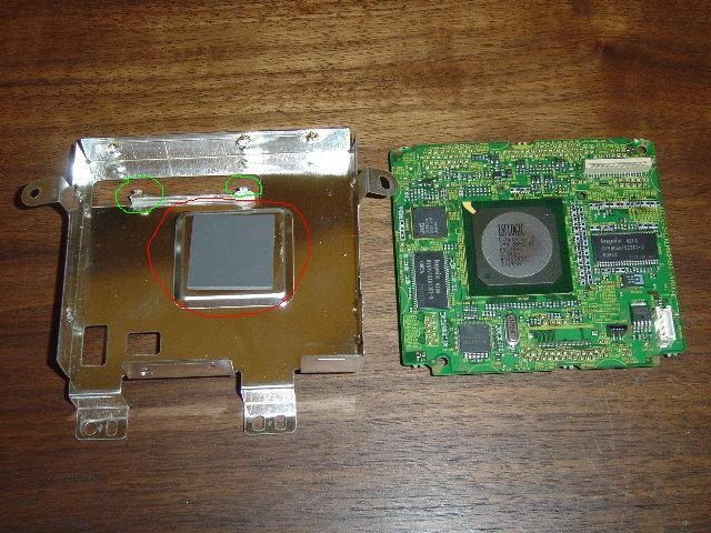
Here is a photo of the thermal pad that can cause overheating problems for the DMN8652 chip. It is circled in red. The tabs circled in green have shoulders that limit how far down into the sheet metal box the pc board can be inserted. Mig-45 found a small gap between the thermal pad and the metal cover in his M10. To do a good job of conducting heat away from the DMN8652, the pad must be in close contact with the chip and metal cover otherwise temperatures can be reached that are near the maximum allowed operating temperature for the part. I believe his solution was to use a thicker pad but it was too late. The high temperatures to which the chip had been subjected for an extended period did permanent damage.
-
Originally Posted by trhouse
Is there a reason why the signal input back into pin 85 ?
I replaced both the thermal pads on the units I had because neither looked to be making contact because I saw no impressions on when I removed it so I put a little thicker pad into them but it really did'nt seem to help them. I also have a Dr-MV5S
which is supposed to be the second generation of the DR-Mv1s. I disassembled that unit to see how they changed . They have a new version of the LSi chip and the shield looks to be made out of a different metal,not shiny. They also have the board upside down and the LSI chip has no contact with the dimple on the can what so ever or a thermal pad. I am not sure why they designed it like that. Don't you think their should be some type of heat sink on these chips to dissapate the heat away from the chip? I have noticed a number of these units coming up with a common problem with either no sound or picture and their front display going out which I think could be linked to the LSI chip.
I know what you mean about being careful about putting the resistors on. I did mine under a magnifier and turned the heat low on my iron so I ddin't have to much trouble
but I have had alot of soldering practice and learned from past mistakes. I did remove one of them somehow removing the can which I later found stuck to my solder wick.
Well hopefully that fixes the green line problem on your unit too . My unit was developing them within a 1 hour or 2 of use and it seemed to fix it up. -
The reason the clock goes in pin 2, out pin 86 and back into pin 85 is not uncommon. The two clock inputs are probably for difference types of clock. My guess is that the pin 2 clock input is for an analog, sinewave clock. This type of clock is often specified as being able to deliver a certain amount of power to a given load like 50 ohms. The DMN8652 probably converts the analog clock input to digital clock levels at the pin 86 output. Digital outputs are specified as having a maximum low level ( representing a "0" ) and a minimum high level ( representing a "1" ). For example, +0.7V might be the max. low level and +2.5V the minimum high level. Some systems will have a clock with a digital output so they do not need to use pin 2 or 86 but can go directly into pin 85.
I am very surprised that the LSI chip in the MV5 does not have any heatsinking. Do you have any way of measuring the temperature or even putting your finger on it to see if it is getting very hot? I tested the temperature of the M10 LSI chip while mounted in the housing with the thermal pad and the housing temperature was 58 degrees C. today. The ambient was 27 degrees C.
My mistake with the chip resistors was not using an X-Acto knife to scrape the plated ends a bit to clear off any contaminants so solder would adhere quickly. I did that with the second resistor and it went smoothly.
The M10 has been operating continuously now for about 24 hours without either green lines or loading appearing. When the unit first came in, it worked for more than a day before either appeared so I will wait for awhile longer to see if it they are really gone.
[edit] I checked the required input levels for the SDRAM chip. They are max. low level = 0.8V and minimum high level = 2.0V. The SDRAM clock line has a 470 ohm resistor in series with it where the JSP8059 AD/DAC chip does not. That would appear to mean the JSP8059 requires the higher drive level from the DMN8652. The JSP8059 has a 16 bit output which goes to the SDRAM.
This might explain why the lines appear. For example, if the JSP8059 loses clock cycles, the 16 data lines to the SDRAM will not change. The SDRAM will clock in the same fixed data during the time the JSP misses clock cycles resulting in fixed sequentially data which when clocked out looks like a line or partial line. -
No I don't have anyway to measure it . I was thinking about putting a heat sink to draw the heat away from it somehow. I notice on all the LSI Domino chips they have the top metal slug meant for that purpose. Almost seems like a blatant way to cause an early failer of the unit. Panasonic has a hink sinking on theirs as does even the Apex recorder that I have which uses the LSI chip .Originally Posted by trhouse
What is the job of the JSP8059 ?Originally Posted by trhouse
That sounds like a good explanation . Whats kinda strange is the way it slowly appears and then unplugging it for a few minutes would restore functionality for a bit of time.but maybe like you said when it reaches a certain temp. its output goes down enough to start causing problems.Originally Posted by trhouse
 Quote
QuoteSimilar Threads
-
HOT DEAL: St. Louis Craigslist - $75 JVC DR-M10 DVD Recorder
By jbd5010 in forum Off topicReplies: 2Last Post: 16th Mar 2011, 08:21 -
problem recording with jvc dr-m10
By restauroman in forum RestorationReplies: 3Last Post: 28th Feb 2010, 11:47 -
JVC 'loading' repair details
By Jack Africa in forum DVD & Blu-ray RecordersReplies: 8Last Post: 13th Apr 2009, 01:19 -
JVC DR-M10 help
By colt4523 in forum DVD & Blu-ray RecordersReplies: 1Last Post: 20th Mar 2008, 06:53 -
QUestion about JVC HR-S7600 repair...
By fireballtp in forum RestorationReplies: 5Last Post: 19th Nov 2007, 01:12