


I noticed one of my VCRs is making a strange "chew mark" on one edge of the tape. Turned out to be my Sony SLV-575UC. I've also mentioned in the past about a jumpy picture and am beginning to think it may be related. I got to admit, I'm pretty decent with repairs (I fixed this VCR once before). My question is, "What exactly do I need to do?" I plan on taking the cover off and watching the tape path and trying to determine where the snag (no pun intended) is. Anyone have any ideas?
Try StreamFab Downloader and download from Netflix, Amazon, Youtube! Or Try DVDFab and copy Blu-rays! or rip iTunes movies!
+ Reply to Thread
Results 1 to 30 of 47
Thread
-
-
Video Restorer

- Jun 2003
- dFAQ.us/lordsmurf


The heads are out of alignment. This is technically called "FEATHERING" of the tape. I take mine to an authorized shop.
Want my help? Ask here! (not via PM!)
FAQs: Best Blank Discs • Best TBCs • Best VCRs for capture • Restore VHS -
You'd need to check tape path especially rollers on both sides of the video head. Often, when you move one you need to readjust the other as well, so be prepared it may take a bit longer then you anticipate. You would need to make a tool to adjust the rollers (grind out a bit of the middle of the flat screwdriver). Best one would be non-magnetic. Try adjusting rollers at a slower - LP, and even slowest speed - EP (once you eliminate bending of the tape edge). Adjusting at lower tape speed is much more precise. Pay attantion to playback as well as recording on all speeds.
-
I`ve worked on lots of that model number sony for that problem which is the take up arm that swings the tape past the pinch roller get stiff and needs to be taken out and cleaned and relubed and realigned.Only do this if you know how to realign the tape path cause if not set right it will skew the tape worse.
Heads do not get out of alignment in vcrs,its usually the tape guides that get loose and carry the tape up or down further in the tape path but thats not the problem with these sonys,its always that take up guide arm that gets stiff which causes the tape to skew and cause the picture to flip and jump and start eating tapes.I think,therefore i am a hamster. -
That load arm is exactly what I fixed the first time. I didn't do any kind of precise alignment to it or anytihng thoughOriginally Posted by johns0


-
Thats were your problem is,you have to align that arm so that the tape rides exactly when its travelling thru the pinch roller,look at the tape when its going thru the pinch roller and notice where its being creased,adjust the nut that holds the arm up or down so that the tape rides evenly with no folding or creasing and is perfectly flat on the pinch roller.
You have to make this adjustment when the tape is running so use a junk or test tape and be very careful you dont lose grip of any tools which can damage the tiny heads on the drum.I think,therefore i am a hamster. -
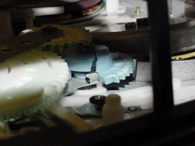
I think I got that problem under control. I just loosened the nut on the load arm, I guess it was too tight. I think I have another problem though. Look at this picture:Originally Posted by johns0

What I loosened up is in blue and my other concern is in green. I've seen the tape actually hang up behind it and not get pulled around the video head.
-
It would have been best if you adjusted that nut in the blue so that you saw that it straightened the tape path going thru the pinch roller but you might have aligned it good enough,the green area you`ve shown is another problem that can related to that takeup arm,that takeup arm should swing freely with no stiffness at all.Sometimes a faulty tape can prevent the tape from loading and going around the head drum.
I think,therefore i am a hamster. -
Speaking of VCR repair... I've got a Panny AG-1970 that plays tapes, the audio is OK, but the picture is somewhat garbled and it is black and white. Tracking adjustments don't help. What could be causing this?
-
Sounds like either the heads are worn or dirty or theirs a problem with the head amp,try cleaning the heads.
I think,therefore i am a hamster. -
Yes, I Know

- Jul 2003
- ...in and around the lake
-
fmctm1sw,
Just got your PM, sorry that I was out for a couple of days from here and didn't get back to you.
I just so happens that I decided to dig out my SLV-555UC deck from the piles in my garage, and decided to fix it. It'd been in storage for a while and it had worked the last time when I packed it up, but when I tried it after I moved, it no longer would play.
The mechadeck is the same in both the 555 and 575, I have one of both. The 575 became a parts machine, although it's one year newer, I prefer the direct loading slot on the 555 (no door to open when inserting the tape).
Once I got into it, I saw the problem right away. The left tape guide was not moving far enough to wrap the tape around the drum. Hmm. It was just moving about halfway, enough to partially load but not enough to actually be able to play the tape.
Might be the same problem you're having. When you look at the left tape guide in your picture, does it move all the way to the back of the slot it travels in? (see picture)

As it turns out, after I disassembled the entire mech, I found the problem. The drive gear for the left guide had snapped in half! No reason, other than age. It wasn't sticking or anything, it just got old and broke under stress. Lucky I had my parts machine (the 575) and was able to take it out and replace it.
You'll know if the gear broke, by just observing the guide like I noted above, if it doesn't move all the way up, it's not going to play. Take a look and let me know.
R.
EDIT: I don't know what's going on, but I can't get the picture to post, so I'm going to try making a new post with just the picture only.Ethernet (n): something used to catch the etherbunny -
Yes, I Know
- Jul 2003
- ...in and around the lake
-
[img]https://www.videohelp.com/forum/images/guides/p1031631/vcr1.jpg[img]https://www.videohelp.com/forum/images/guides/p1031631/
Trying again... Ethernet (n): something used to catch the etherbunny
 -
Yes, I Know
- Jul 2003
- ...in and around the lake
-
Well, something is wrong, but I don't know what. I've never had any problem posting a picture before. I just took your picture that you posted and added text and arrows, and it refuses to post. I have no idea why.
You can see the strange path in the post just above this one, who knows what happened here. I just typed [ img ] vcr1. jpg [ /img ] (without the spaces, of course) and it won't work. I only added the number "1" to what you named the picture, so there wouldn't be any confusion by the board.
It still refuses to work.
Anyway, you should be able to understand what I was talking about, that the left side loading guide (on the left in your above photo) should move all the way to the top of it's travel slot, just like the one on the right. If it doesn't, you have a problem with the gear like I mentioned. Take a look.Ethernet (n): something used to catch the etherbunny -
Yes, I Know
- Jul 2003
- ...in and around the lake
-
Oh, and one more thing: I noticed that the timer on the 555 runs out at the end of this year. In other words, no way to use the timer function after December 31, 2004 on this unit. On the 575, the timer runs out of years in 2005. Don't know if you noticed that or not, just thought I'd mention it.
I guess Sony thought these machines would never last 18 years, so they didn't program the clock to go past that point!
Like it would have cost them extra to make the clock go to 2025... go figure.Ethernet (n): something used to catch the etherbunny -
Thanks Roundabout (and everyone else). Take a look at the guide on the left. Doesn't it look "further ahead" of the one on the right? I've watched one of my tapes get hung up on it and another get stuck behind it. Can I make it go further back?
-
It goes all the way up, but seems "loose" or "sloppy" and doesn't seem like it goes back far enough....Originally Posted by Roundabout
-
Yes, I Know
- Jul 2003
- ...in and around the lake
-
O.K., trying to post another picture now...
 Ethernet (n): something used to catch the etherbunny
 -
Yes, I Know
- Jul 2003
- ...in and around the lake
-
Although it's hard to tell, because your picture was taken at a little bit different angle than mine, it seems like you could be right. The guide should be all the way to the back of it's travel area, and it doesn't look like yours is. I think you may have the same problem I had, the blue gear on the bottom that drives the guide is broken or out of alignment. Most likely broken. You'll need to take the bottom off the unit and take a look. In order to do so, you have to remove the PCB that is mounted to the bottom of the chassis. We'll get more into that later. For now, you need to look at the mech when you get a chance.
Ethernet (n): something used to catch the etherbunny -
I'm by no means an expert, but it's my understanding that when the roller guides fully engage they should be snug up against the v-stops and not have any "slop" in them.Originally Posted by fmctm1sw
-
The guides should definitely lock into place, this is very important. The loading gears bending and or breaking is common on that assembly.
-
Yes, I Know
- Jul 2003
- ...in and around the lake
-
fmctm1sw,
Any luck? Did you find out what is going on with your VCR, since the forum was down over the weekend and you couldn't reply?Ethernet (n): something used to catch the etherbunny -
I'm still working on it. Kid's just started school, been busy too. I may have a chance this weekend...
-
 This sucks!
I found repair parts here. Now, how do I get that circuit card out? It seems real tight over by the connectors. I don't want to yank..
http://www.iglou.com/studiosound/mbk-89.htm -
Are you sure you don't want to talk to a repair guy?
-
Slide a screwdriver under the board where it plugs into the capstan motor and gently pry up there, that is where it will be held the tightest. Pull the carriage out and the board will come out a little easier. If you unsolder the tape end sensor on the left side in the position you have it and pull out the plastic assembly the board will lift up and out of the way easier, but soldering them back in can be a pain. There will be a large gear that will have to come out to get the broken gear out that has 3 plastic levers that have to be aligned when put back in. Unless you are comfortable working on stuff, I don't know if I would recommend trying to fix it.
-
Unless you`ve repaired vcrs for gear alignments and know what you are doing then i wouldnt work on this problem.Just remember to mark the gear teeth positions and that you have to pull the bottom pcb off and remove the whole ass'y from the top.The main connector from the pcb to the chassis assy just pulls apart.
I think,therefore i am a hamster. -
Yes, I Know
- Jul 2003
- ...in and around the lake
-
So I was right, the gear is broken, except in your case, it's badly cracked, and in my case, it snapped into two pieces. Funny it should happen at the same time as yours, all these years later. Guess 18 years of loading and unloading stresses this plastic and it just snaps.

Anyway, I noticed the website you are getting the parts from has a very good instruction on the alignment when replacing this gear, I think you can handle it. It's a little tricky when putting the large cam gear back on, but if you follow the pictoral instructions, it's not too complicated.
I assume you've already removed the four screws and released the plastic holding clip at the bottom edge of the PCB (shown in this first photo).
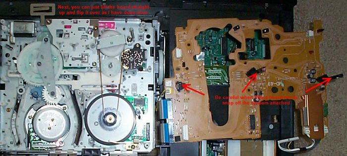
Next, you only have to unplug the drum connector at the bottom left of the board, as I've shown. Then lift the board straight up and out. There is a connector that is mounted to the PCB and it plugs directly into the capstan motor connector, so it's very important the pins aren't bent when you lift the board out. Just lift it carefully straight up, you will notice on the bottom right side the extra resistance of this connector. Just pull gently and it should come right out. You don't even need to unplug the flex cables (the white flat wire connector on the right edge of the PCB). As you lift the PCB up, make sure that the long plastic sensor holders that protrude vertically from the PCB clear the chassis before you "roll" the board over as shown in my second picture.
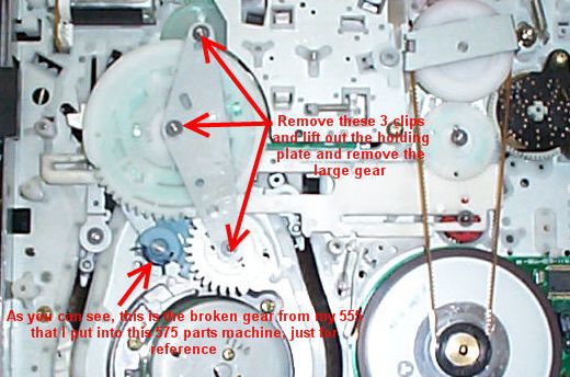
After that, remove the holding plate clips and holding plate as shown and lift the large cam gear out. Then you can remove the clips holding the supply side loading gear (the blue one) and the take up side loading gear (the white one). (Edit: sorry, there is no clip on the take up side loading gear, as it is held in place by the holding plate.) In order to remove these two gears, you'll have to remove the clips holding the arms attached to them and the guide assemblies as shown below:
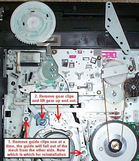
Note that the guides will fall out from the other side of the mech when you remove the clips that hold them to the arm, so note which is which for when you put them back in (very important!). Then you can just lift out the gear and arm assembly together and then remove/replace the broken gear.
Sorry my pix are a little fuzzy, my digital camera isn't the best and when I reduced the size to fit on the forum they got worse. I think you can get the idea, though, and it's not that hard to replace this gear after you've done it a few times. Shout back if you have problems.Ethernet (n): something used to catch the etherbunny -
If it's a newer assembly there won't be the same connectors on the board and it will be harder to get out. If it doesn't have those ribbon cables don't bend it all the way over like that or you will break the connecters and be screwed. If it has the metal connectors don't take it much past straight up and down, if any of the connecters break you will have to solder wires from board to board.
-
This is where I stopped last night. I got the one on the other side out but this one was tougher. I stopped before I yanked too hard. I still got to buy the gears from that site. I may buy the other gear as well so I don't have to do this again. As for the "take it somewhere to be fixed" posts, I probably would if I were not in northern Japan. The availability of repair places around here are pretty thin...Originally Posted by Roundabout

 Quote
QuoteSimilar Threads
-
VCR/VHS playback - lines on picture...vcr alignment problem or no?
By daysaf00 in forum CapturingReplies: 1Last Post: 23rd Jan 2012, 00:54 -
Specific Panasonic VCR buying advice needed
By Sainsbo_McManus in forum RestorationReplies: 8Last Post: 28th Nov 2011, 19:30 -
Help needed with Video Capture - No VCR recognised on PC
By ULscot in forum CapturingReplies: 7Last Post: 14th Nov 2010, 12:14 -
Mode switch alignment - requst to Panasonic VCR owners !
By abbymat in forum RestorationReplies: 0Last Post: 29th Apr 2008, 13:27