


Hi,
I'm hoping you guys can help me out here.... I just bought an older Super VHS VCR Panasonic VCR from the late 90's... I have another one just like it (same model) but the one I got recently has some issues, was hoping you'd help identify. I have uploaded a couple of 1 minute videos, links below.. I have correctly cleaned the heads prior to use (as I do for my other VCR's), so I'm not a total newbie at this. I have hooked up the VCR with the issue identically to the other one (which works fine). The problem is as follows: (1) you'll note in the 1st video that all I'm doing is switching channels (tape is not inserted) and you'll see what looks like some kind of interference in the background (between channels). Again, I compared the same other model VCR, similarly connected and it's fine so I know it's only this one that has the problem. Every input / output causes the same problem. The 2nd video shows me playing a recorded tape (that I taped off cable) - see the same problem but seems to be more pronounced also on the black/white movie at the start, like waves of streaks.. (Again, the heads were manually cleaned very well using paper strips and 99% alcohol until no dark oxide was present...). This problem occurs when watching TV through the VCR and also when something is taped. So I see this as NOT a recording problem but something else but as you can see is significant. Pre-recorded cassettes seem to play fine though.
Another problem is that whenever a tape is inserted and is otherwise playing or FF or REW, an onscreen prompt displays "no cassette - please insert a cassette" (even if cassette is playing etc..). It doesn't seem to affect the playback or anything but why is it showing up? Are those two things related to some kind of electronic problem?
Here are the videos, thanks for viewing:
https://youtu.be/kp-yNOjsDOo
https://youtu.be/LHKSyBb2Yks
Any idea of what this could be?
Thanks again.
Try StreamFab Downloader and download from Netflix, Amazon, Youtube! Or Try DVDFab and copy Blu-rays! or rip iTunes movies!
+ Reply to Thread
Results 1 to 24 of 24
Thread
-
-
I have this identical problem on my Panasonic PV-S4990 and have tried for fifteen years to fix it. I even went so far as to replace the head and then to re-cap the power supply, even though I was 99% certain neither would fix the problem (I was right). I still think it is something not quite right in the power supply, but I gave up trying to fix it. I should also note that the unit does a really lousy job playing EP (6-hour) tapes (i.e., the problems are worse, and include chroma rainbows around those streaks you are seeing), and seems to have noise on the Hi-Fi audio, especially at slow speeds. It would be informative to hear if your unit also exhibits either of these issues.
I'll be interested if someone comes up with the answer. I wish I could be of more help, other than to confirm that it is, perhaps, some sort of common problem with Panasonic's design. -
No problem with tapes from other machines, so your heads and transport are not involved. The bug appears to be in the input circuitry. If you wiggle the input cable where it's connected, does the noise change or go away? Look at the circuit boards and check for loose connectors and loose/broken wires. Look for capacitors with open tops or discoloration on/around them. Ensure the screws holding circuit boards in place are snug (but don't overtighten them). Beyond these measures, you really need a service manual and test equipment to track down a failing part or incorrect voltage.
Other issue is failure of the cassette-in detector. Something is not seating or switching or the electronic path from that part has a failure. Usually this is a mechanical problem. -
Thanks very much for sharing your experience. The Panasonic model that I have is the PV-S9670. I can't tell if my unit has any audio issues as you describe or any chroma rainbows. It's mostly just, what looks like smudges, blotches or streaks and not a steady solid picture, as mostly seen between station changes and some of the black and white movie clips...Originally Posted by johnmeyer

-
Thank you very much for your help. I will try to do a check of all the things that you ask about and report back if anything changes or if I find something.Originally Posted by JVRaines
-
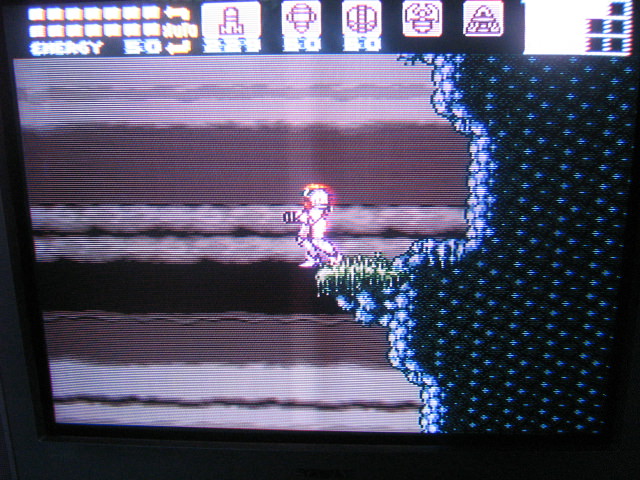
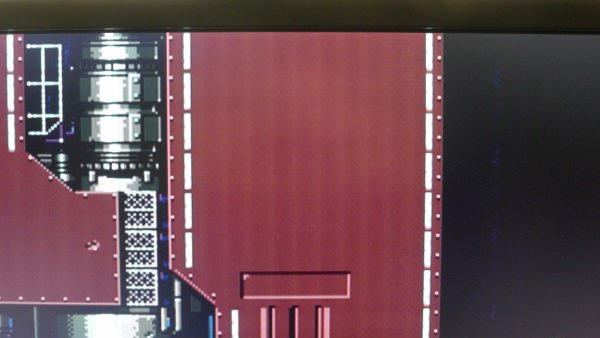
So that there's no misunderstanding of the issue, here's some screen capture images of the problem.
-
I don't know how this devices are hooked up, from where you're getting the signal from? RF? Composite? (Yellow RCA connector)
In general, this is caused by a high frequency interference resonating at the video frequency.
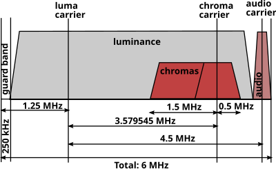
The interference has no chroma, so it's around the luma range around the 4.5 Mhz bandwidth. This is not a easy fix, you have to separate the device in different modules and check every single one of then. Like the power supply area, the RF area, the heads signal amplification area and the video out area. In between this, you have a heavy noise generator, the drum and capstan motor.
To avoid the noise and interference to infect other areas the engineers use LC filters to shunt or block these out, you see a lot of LC filter in the RF area and a mix of them around the board, is very rare to see any issues with inductors but is pretty common to see electrolytic capacitors to dry out, this components have a life span around 10 years, after that is hard to tell how long it will last. For a device from the 90's, you need a full recap, that means to change all the electrolytic capacitors, decontaminate the board with a Isopropyl alcohol bath before installing new ones.
Another important thing to care about and many doesn't, any equipment that has a switched-mode power supply (SMPS) requires low ESR electrolytic capacitors at the power supply it self and along the power lines, all the rest can be standard ones.
Last but not least, ALL decoupling capacitor's around the integrated circuits has to be checked, if this capacitor is a electrolytic one it must be a low ESR type. This has to be done because a decoupling capacitor suppress high-frequency noise in power supply signals and we are dealing with a high-frequency interference. Another thing that less experience technicians don't know, ceramic capacitors around this area has to be tested because ceramic capacitors loose capacitance over time.[1]
There's no need to change every single ceramic capacitors on the board, just the ones doing decoupling or around circuits related with the issue, if necessary.

Again, this is not a easy fix but it's a pretty common issue with devices of this age.
Extra reading.
http://www.ee.co.za/article/thermal-stress-capacitors-failure-prevention.htmlLast edited by amaipaipai; 28th Feb 2018 at 06:15.
-
Incredible info, thank you. I just wish I had the knowledge to do this...
-
I don't think his analysis is the correct diagnosis for the visual disturbances you have posted. Decoupling capacitors are there to make sure that voltage spikes don't cause the logic in digital circuits to glitch. They are really, really tiny and are designed to filter out very tiny, very high frequency glitches. Their actual capacitance value is extraordinarily small. I don't see how failure of these bypass capacitors could cause the interference patterns you are seeing.
I am not aware of any wholesale problem with these caps, unlike the famous debacle with the huge lot of bad electrolytic capacitors in the late 80s and early 90s that affected millions of consumer electronic products.
As I said in my earlier post, I have the same interference patterns with my Panasonic PV-S4990 VCR (which I still have and it still works, sort of). I did re-cap the switchmode power supply (with low ESR caps), and it didn't help at all. As I also posted above, this didn't surprise me because when the caps in a switchmode power supply go bad, it won't start up at all, or the voltages coming out of it go out of regulation.
I think there may be a simpler explanation, but the answer will have to come from someone who has actually been a service tech and who has worked on Panasonic equipment.
The answer is out there somewhere ... -
Yeah, you're right, it might be a simpler answer, especially that you're the only guy so far to have worked on a similar unit with same problems... Yeah, it'd be cool to get some perspective from a Panasonic tech or similar... I don't like unsolved mysteries (other than the show)..

-
Like I said, it's a problem in the input circuitry, perhaps an amplifier. Looks like a part has failed or a connection is broken. You need the service manual and a scope to track it down.
-
As stated before, this is a well known issue, the thickness of this bars and interference is subjective, it dependes on many things but the issue is the same.
And only a few of us knows how to deal with it, example:
http://etim.net.au/av-driver/pcebars/
Again, this is not a easy fix, the person that will deal with it need the knowledge, he/she need to know how to work around this with a oscilloscope and other tools. Without the knowledge, even with the right tools, the technician will never see or understand what is wrong and why it happens. It can be the Input, Output, pre-amplifier, the signal amplifiers, signal buffer, can't tell. Is impossible to pinpoint a place and tell "it's here", it can be anywhere, of course there are the "usual suspects" but the person that will deal with it, will have to track it down and figure it out where is the source that is causing this. -
If the posted example are not enough, have another one.
This was caused by a bad decoupling ceramic capacitor.
https://youtu.be/8TnScaNWo0M?t=35s
-
The "jail bar" noise in that video looks completely different from the artifact posted by the OP.
Interesting write-up, though. -
The root cause of that vertical interference is the same, it doesn't need to have the same look.
Last edited by amaipaipai; 2nd Mar 2018 at 04:44.
-
I am very interested in the outcome of this discussion as I am about to recap a RTV-925 (NV-FS88), so while I am replacing the SMD electrolytic caps I would like to know of is worth my while replacing the ceramic caps too?

I have the basic test tools/skills, and an ESR meter too, so any first hand advice will be appreciated.Last edited by wim72; 2nd Mar 2018 at 04:15. Reason: extra comment.
-
When I do a maintenance like this I check the decoupling caps and replace then for a reason, in 99% of the time this interference will show up sooner or later and your client will blame you for it because you was the last one to mess with it, you know the talk "it was fine before you fixed or messed with it". Since you already have the unit open, it worth the time to take a look at it.Originally Posted by wim72
There is not need to check all of them, only the ones related with the signal path.
A good advice?
Use ESD SAFE devices, tools and soldering workstations.
Get a good electric desoldering pump. (thanks me latter)
Use tweezers for desoldering this caps, is clean and fast.
You can use bigger values for this caps.
Think outside the box, don't take everything for granted, keep your mind open!Last edited by amaipaipai; 2nd Mar 2018 at 09:55. Reason: misspelling
-
I am very familiar with low-ESR caps, and there is no option: you MUST use them when re-capping a switchmode supply.
But, what are "ESR SAFE devices, tools and soldering workstations"? I wasn't aware that tools and workstations contributed to a capacitor's equivalent series resistance (ESR).
I'd love to know what these are so I can update my equipment. -
That's a typo, is ESD SAFE equipment like this one.
-
Ah, that makes more sense. And, it's good advice.Originally Posted by amaipaipai
Looking at that link you provided, the one thing I've wanted to get for years is a good desoldering tool. I use a spring-loaded, plunger type sucker, and then clean up with desoldering braid. This works, but it is slow, awkward, and often subjects the PCB and component to a lot of heat (I often want to re-install the component if it tests OK once removed from the circuit).
I'd love to get a proper vacuum pump desoldering iron tool, but the good ones always seem to be many hundreds of dollars. I've seen a few under $100 tools, but I suspect they might be junk. I don't do this for a living, so I can't really justify spending too much, but I'd certainly be willing to spend $100 (or a little more) if someone has a recommendation. -
Over here I use Hakko, my vacuum pump is so old I can't see the model anymore, it's from late 80's or early 90's model. I've never changed the internal ceramic heater or the motor pump. Tools like this are a investment, you can do your job fast, better, with quality and precision. The pump is so strong that it leave nothing on the terminal holes, it suck all the solder out with one click.
I've never used other brand so can't help you with that, for those that don't know what we are talking about, jump to 21:10
https://www.youtube.com/watch?v=Ft50m8UU5WQ -
Thanks so much for that info, and apologies to the OP for taking this OT. Yes, the Hakko seems to be what a lot of people recommend. Maybe I just need to suck it up (financially) and get one.
[edit]I skimmed through that video and near the end he desolders some motherboard caps. I have a motherboard that I got about 1/4 re-capped and then gave up because even with my Weller temperature-controlled soldering iron, I couldn't get the solder hot enough to get it to flow. It sometimes took several minutes to get the ground side of the cap unsoldered. In the video, the guy doing the demo had problems as well, but by turning up the heat and letting the iron stay on the board for 10 seconds, it worked. I could almost justify the cost just by being able to get my old computer (which is hard-wired for my film capture system) working again.Last edited by johnmeyer; 2nd Mar 2018 at 17:18.
-
No problem!
Motherboards are build with multilayer sheets of fiberglass , they are very thick and they can dissipate heat very fast, to work with boards like this you have to preheat them using a oven, a special jig and do some procedures to heat up the board in a control manner because if the board is heat up too fast it start to warp and when it start, it can break internal paths, interconnections, etc.
With motherboard maintenance we use something like this:
http://www.hakko.com/english/products/hakko_fr872.html
You heat up the board to about 100 ºC (212 ºF) then you use your tools, the solder will melt like a butter.
Why 100 ºC? (212 ºF)
Because some components like electrolytic capacitors has thermal threshold of 105 ºC (221 ºC), that's why control is important, if you don't have it, you can set it to about 90 ~ 95 ºC (194 ~ 203 ºF)
With the correct tools you can do a full recap on a motherboard in less than 30 min instead of 2 or 3 hours, you can work and replace parts on iMac's boards very easily.
Have a good one!
 Quote
Quote

GIGABYTE AM3+ ATX GA-990FXA-UD5 R5
AMD FX-8350 Vishera
Seasonic White Snow 1050W
Asus essence STX II
Corsair Vengeance 16GB (2x8GB) 1866MHz DDR3 CL10 Red CMZ16GX3M2A1866C10R
Be quiet Shadow Rock 2
15TB Raid 0 HDD")
Similar Threads
-
Panasonic VCR Settings
By Tafflad in forum CapturingReplies: 26Last Post: 28th Nov 2023, 14:36 -
Panasonic FS200 Issues
By Topsy in forum RestorationReplies: 3Last Post: 29th Nov 2016, 09:21 -
VCR comparison Panasonic NV-FS200(AG 1980) VS Panasonic NV-HS1000
By JoseD in forum RestorationReplies: 32Last Post: 18th Apr 2016, 08:30 -
ID this VCR (Panasonic AG series)
By fmctm1sw in forum Newbie / General discussionsReplies: 4Last Post: 8th Nov 2014, 02:49 -
Two VCR's, one has contrast issues?
By Masejoer in forum RestorationReplies: 7Last Post: 16th Feb 2014, 20:21