


a wife")
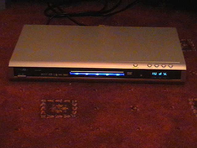
Yamada DVX-6600 guide to making the blue strip glow.
By Underwurlde. 20th Jan 2005.
Abstract
This guide will explain how to make the blue strip under the DVD/CD transport loading tray illuminate.
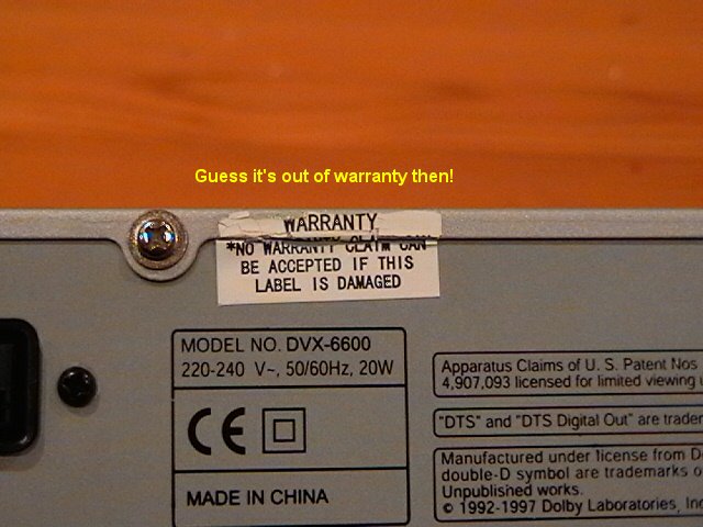
You will obviously need to take your precious player apart, possibly voiding the warranty.
As an aside, since we are about to take the player apart I have also described how to adjust the IR sensor
for improved remote control reception.
This guide assumes some basic electrical knowledge and some soldering skills.
There is the chance of course that you could end up damaging your unit, especially if you are unsure of what
you are doing.
-> Y o u H a v e B e e n W a r n e d ! <-
Parts
PCB Strip board, 5 holes wide, 44 holes long (copper strip length).
5 blue or white LEDs either surface mount or through hole.
5 330 ohms resistors either surface mount or through hole.
Some wire.
Some nounce.
Total cost: Less than £5.00.
Terminologies
LED = Light Emitting Diode.
PCB = Printed Circuit Board.
PSU = Power Supply Unit.
SMT = Surface Mount (component) as opposed to through hole (THP).
VFD = Vacuum Filled Display. i.e. the display on the front of the player sometimes mistakenly referred to
as an LED display.
IR Receiver = Infra Red Receiver that detects signals from the remote control.
Disassembling The Player.
!! WARNING !!
240V AC mains is present inside the unit!
UNPLUG UNIT FROM MAINS. DUE TO NATURE OF SWITCHING PSU, WAIT 10MINS BEFORE PROCEEDING
Remove the cover:
1) Remove 2 pairs of shiny screws on either side of player. Remove two shiny screws on left & right sides
of the player at the rear.
2) Try this: Use a lighter & heat up warranty seal & try to prise it off the cover using a scalpel blade
(informed of this trick after taking my player apart L ).
3) Remove final central shiny screw at rear of unit.
4) Remove cover by lifting up at rear of unit & then sliding tab out from under front panel.
Remove the front panel:
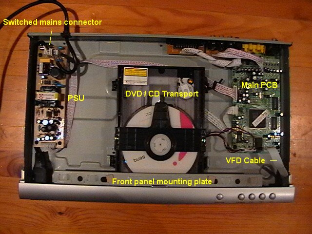
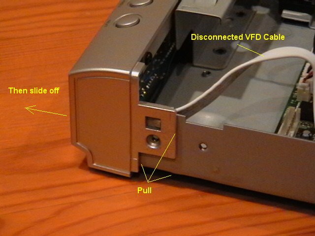
1) Disconnect VFD cable - just pull it out the connector. Remove mains switch cable (black cable running
down left hand side of unit, inside of which is a black and a white cable) by squeezing the connector &
pulling it out.
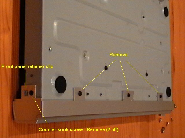
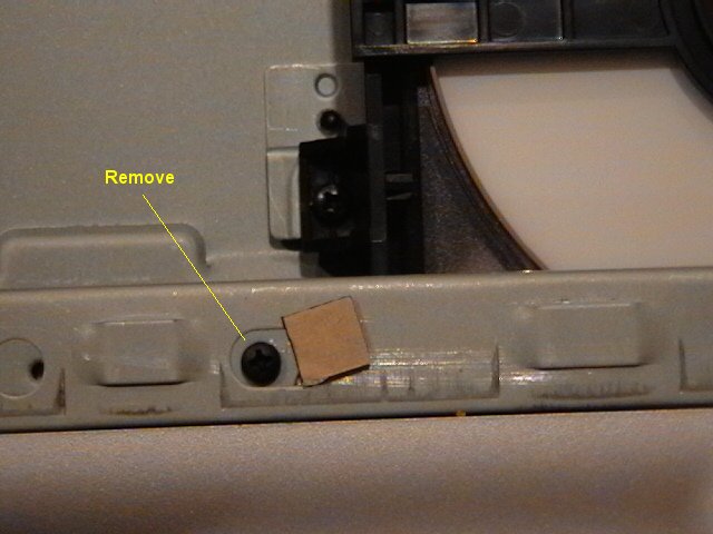
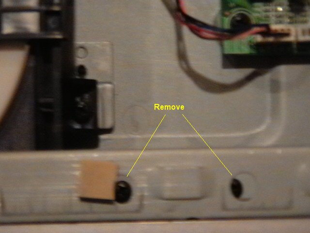
2) Turn unit upside-down & remove 3 black screws. Remove 2 black counter sunk screws on either side of the
front panel (next to the front panel retainer clips).
3) Turn unit right way up again & remove 3 black screws either side of DVD.
/CD transport on mounting bracket. Note how short they are.
4) Slide off front panel, right-hand side first by gently pulling the catch over the formed bump in the
chassis. Repeat for the left-hand side. Slide entire unit off.
Disassemble front panel:
1) Remove front panel mounting plate by removing 4 black screws.
Reposition IR receiver. (Completely ignore this step if you wish).
Might as well do this now that the player is apart!...
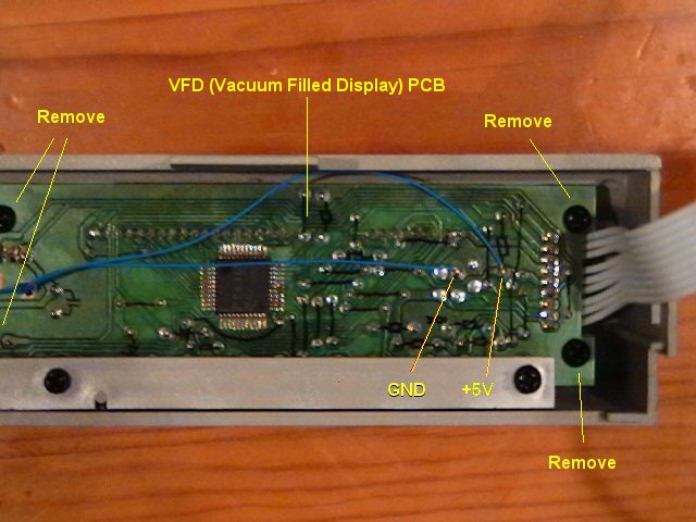
1) Remove 4 black screws on PCB. Lift out, top end first, the VFD PCB.
The picture below shows 2 blue wires connected to +5V and GND on the VFD PCB – ignore this for now, this is
part of the mod explained later.
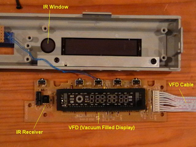
2) On my player the IR receiver pins had not been cut short once soldered onto the VFD PCB so I resoldered
this component maximising on the extra length of these leads.
3) Using some nounce & a pair of pliers to reposition IR receiver closer to its window. It did make a
noticeable difference when using the remote on my player!
I have seen suggestions on the Internet that further improvements to IR reception can be made if the shiny
coating on the window is scratched off! By all means take this opportunity to totally ruin the looks of
your player & scratch away but this is totally unnecessary. I have found that the limiting factor with
regards reception is now purely down to the remote control & not the player. I purchased a
OneForAll remote control & I can ‘hide’ it behind my hand & it still works.
4) Once done, put VFD PCB back in place & screw in 4 black screws removed.
Making an LED Illumination Board.
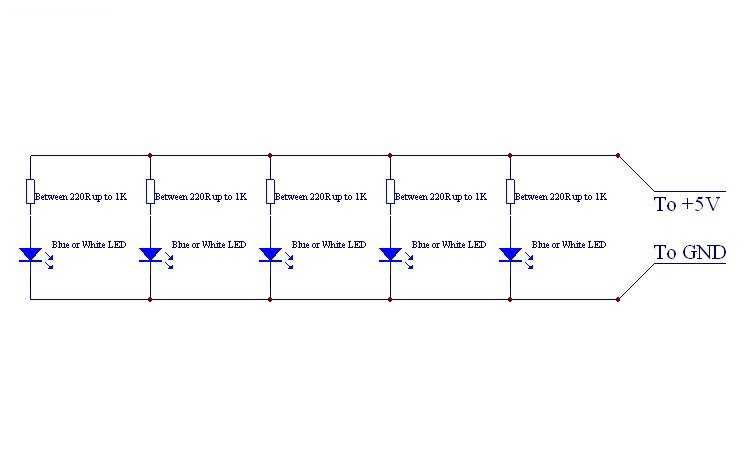
Circuit Diagram.
The picture below shows a circuit diagram or schematic of the LED board that will be constructed on the
strip board:
The resistor values can be anything from 220 ohms to 1K ohms – the lower the value the brighter the light
emitted from the LEDs. I chose for my mod 330 ohms. You can use SMT (surface mount) or THP (Through Hole
Plated) parts for the resistors and LEDs it does not make a difference. I used SMT as they were easier to
assemble.
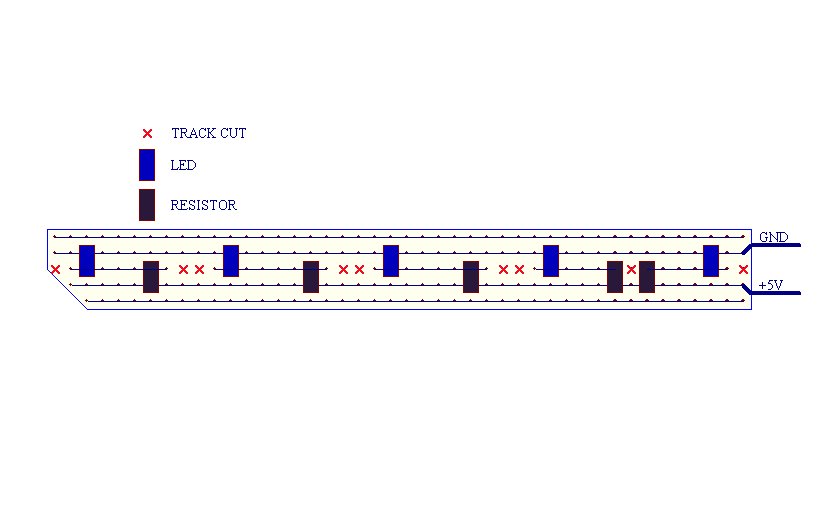
Strip Board
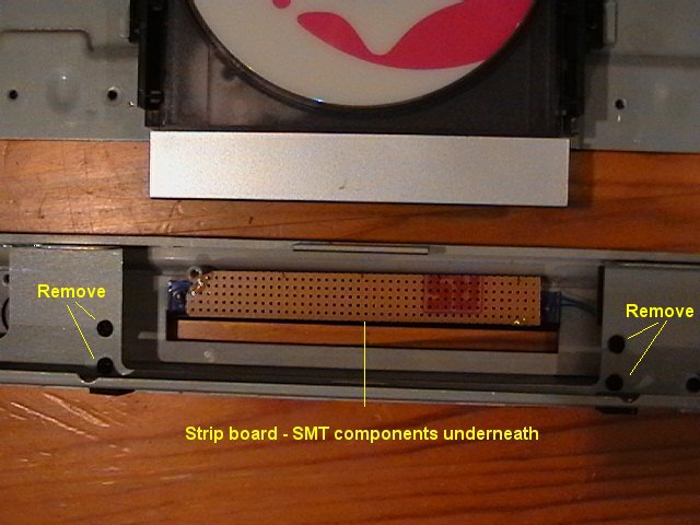
Picture below shows copper-side up of strip board & how I’ve mounted some surface mount LEDs and Resistors:
Notice the notch cut in the corner to avoid interference with a mounting pillar on the front display panel.
The LEDs are placed in such a manner so as to align to the centre of the tubes in the illumination strip
and the resistors are mounted in such a manner so as to not interfere with these tubes. It should then be
possible to mount the strip board flat to the surface of the tubes.
I have shown surface mounted components but the same layout can be used for throughhole (leaded) components.
Note: LEDs do have polarity – if one doesn’t light up in one orientation then simply desolder it and turn
it around. Connecting & applying power to an incorrectly or reverse connected LED won’t damage it.
Mounting the LED Board
I mounted the LED board to the front panel illumination strip by first making sure the LEDs seated inside
the holes and then gluing the board down using a hot melt gun making sure that the edge of the board was
clear of the DVD / CD loading tray hole by at least a couple of millimetres.
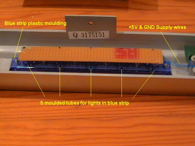
Connecting The Supply Leads
Once the board has been tested and is glued in place, solder the supply leads to +5V and GND on the VFD
PCB as shown in the picture below. Don’t worry if you accidentally get them swapped, as no damage will
occur. (Ignore the ‘Remove’ text).
Looking at the connections on the right of the VFD PCB that the VFD cable is soldered to, counting down
with pin 1 at the top:
1 - ignore
2 - ignore
3 - ignore
4 - GND
5 - +5V
6 - ignore
7 - ignore
8 - ignore
9 - ignore
Done!
If you wish, before reassembling the player & are courageous enough then reconnect the VFD cable and the
switched mains cable connector, plug the player into the mains & switch the unit on.
!! WARNING !! LIVE PARTS – KEEP HANDS AWAY FROM THE PSU
Once done testing, switch the player off & unplug it from the mains and then WAIT for 10 minutes to allow
the rather nasty voltages present in the PSU to discharge. Unplug the VFD cable and switched mains lead
again to ease in reassembly.
Believe me getting a 400V D.C. shock from a switched mode power supply such as the one used in this player
is not a pleasant experience and could kill you! (And yes, I have had ‘belts’ from these types of power
supplies myself in the past.
Once Bitten, Twice Shy – it bloody-well hurts enough to make you puke).
Reassembling the Player
Quick note:
Don’t risk stripping threads – to avoid this, before doing up a screw turn it anticlockwise until it ‘seats’
in the existing thread, only then start to do it up.
1) Replace front panel mounting plate onto the front panel using 4 black screws removed but do NOT tighten
them up – allow the mounting plate to move. Note how the screws sit in groves in the mounting plate not
holes to allow for height adjustment.
2) Offer front panel up to player chassis. The metal front panel mounting tabs go INSIDE the chassis, the 3
plastic tabs on the front panel go OUTSIDE (underneath) the chassis. Align the plastic tabs on the left &
right of the front panel into their channels & push home until it clicks in place. Ensure your new PCB
strip board mod does not interfere with the DVD/CD loader – note how my mod clears the hole for the loader
in the picture above.
3) Replace the two side counter-sunk screws. Be careful not to tighten these screws up too much or you’ll
crack the tabs – finger tight should be enough.
4) Replace and tighten the 3 stubby black screws that hold the front panel mounting plate onto the chassis
(one screw to the left of the DVD / CD Transport, two to the right).
5) Replace VFD cable connector. Push cable flat so it will not interfere when replacing players’ cover.
6) Replace switched mains cable connector & route it under the PSU PCB so that it will not interfere when
replacing the players’ cover.
7) Flip unit over. Replace and tighten 3 remaining black screws that hold the front panel on. Again, do not
over tighten or you may crack the plastic tabs.
8 ) Flip player the right way up & tighten up the 4 black screws on the front panel mounting plate from
step 1) above (this is a bit fiddly).
10) Replace cover, tab inserted under front panel first before lowering rear of the cover. If you’ve
successfully removed the warranty label, WATCH OUT FOR IT!
11) Replace 7 shiny cover screws - do them up loosely first & once they are all in, tighten them up –
3 rear ones first & then the 4 ones on the side.
12) Test the player – hopefully it’ll still work!
13) Finally push the sticky warranty label back down.
You can now sit back and bask in Blue LED Glory.
Good Luck & Happy Modding,
Andy.
Notes
Lights: For this project I used 5 SMT (Surface Mount) blue LEDs that have the effect of making points of
light as you can see if you look at the first picture at the start of this guide. I was hoping for a more
‘consistent’ lighting effect. Because the blue plastic strip is effectively a wave-guide, I could’ve placed
bits of cardboard in the 5 tubes directly in front of the LEDs to prevent this undesirable effect. Some of
you may like this – it does at least look like the promotional pictures of the player I have seen on the
‘net.
As far as I can tell the player was never intended to be shipped with the blue strip illuminated. This is a
cheap player and Blue LEDs are EXPENSIVE!
You’ll note that the LEDs will remain illuminated when the player is put into standby via the remote control
- this is not very professional and I have not found a simple way around this problem yet. However…
The VFD board uses the Princeton Technologies PT6315 VFD controller. This chip is controlled via a 3 wire
serial interface from the main PCB & is used to drive the VFD itself, the 5 push buttons on the front panel,
the IR remote control sensor and interestingly enough 4 unused LED driver ports (on pins 1 to 4).
Unfortunately, after connecting 4 LEDs to these ports they just permanently illuminated the LEDs & did not
go off when the unit was placed in standby. This however does not mean that the players’ firmware can’t be
modified to drive these LEDs so that they go off when in standby (a pipe-dream I know).
Try StreamFab Downloader and download from Netflix, Amazon, Youtube! Or Try DVDFab and copy Blu-rays! or rip iTunes movies!
+ Reply to Thread
Results 1 to 1 of 1
Thread
-
Work you bloody thing....
 Quote
QuoteSimilar Threads
-
Make LG DVX-286 (/ DVX-276) region-free
By joniakaidiot in forum DVD & Blu-ray PlayersReplies: 2Last Post: 12th Mar 2010, 07:33 -
LG DVX 482 H Player and ext. HDD DVD playback
By no-fast in forum DVD RippingReplies: 0Last Post: 11th Mar 2010, 03:33 -
How do I add new subtitles to a existing BLUE RAY
By siopilos in forum SubtitleReplies: 1Last Post: 12th Nov 2009, 09:48 -
Samsung LED S7000 media player limitations with H264
By ye11ow in forum DVB / IPTVReplies: 14Last Post: 11th Nov 2009, 18:21 -
Yamada 5520 DVD Player - Remote
By paulXLE in forum DVD & Blu-ray PlayersReplies: 0Last Post: 18th Aug 2007, 11:24